My wife is working a couple of evenings a week for a tax preparer who used to work for her when she was an H&R Block office manager. Friday night he was taking down his $300 sign out of the window to throw it away because it had a few dark LEDs. She told him no promises, but I might be able to fix it because I do stuff like that every night.
And yeah, she was right.
I’m actually not sure I’ve seen all the failures the sign has to exhibit, but I’ve fixed two overt and two covert. The obvious ones were the dark LEDs in the white “M” and “E.”
The less obvious ones were that the pull-chain switch at the bottom doesn’t shut the sign off, and that the DC power plug pops out of the jack.
Opening It Up
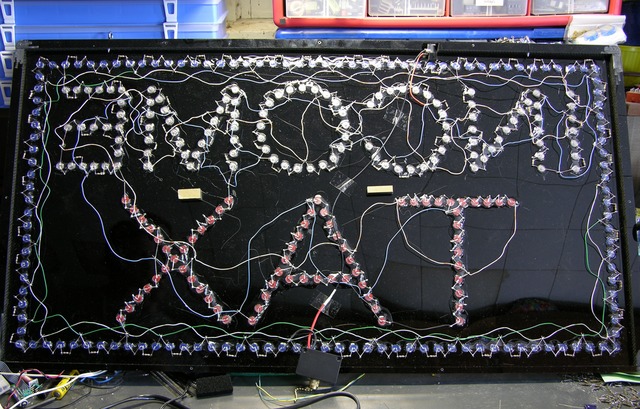
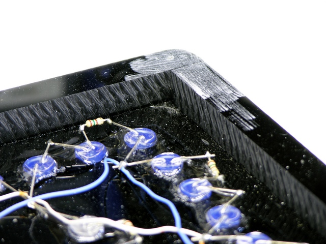
The sign is made of two plastic sheets sandwiching a thicker plastic frame. The front must be glued on, but the back is screwed on for repairability. Actually, given what the inside looks like, I have my doubts that the manufacturer ever considered repair; I suspect screwing the back on was just the first thing that occurred to them.
I’m (mostly) not knocking the schematic — many parallel series chains of LEDs is the only reasonable way to design something like this. And making chains of three each blue and white LEDs but five red LEDs is also reasonable, given the respective voltage drops.
But I do take issue with stacking three LEDs with 3V drops on a 9V (nominal) unregulated power supply. The supply happens to run about 9.7V under the load of the sign, which leaves .7V across the 150Ω current-limiting resistors, hence just under 5mA LED current.
Leaving that low a voltage drop across the resistors makes the LED current (and brightness) incredibly susceptible to variation in the actual voltage of the unregulated power supply: a power supply change from 9.7V to 10.4V seems insignificant but would double the (white and blue) LED current. Worse, a drop from 9.7V to 9.35V would halve it.
Mainly, though, it strikes me odd that the sign is wired with leftover four-pair UTP (network cable). Was this thing built in some guy’s garage with stuff he pulled out of the dumpster at work? (Wait, did I build this thing??? ![]() )
)
Fixing the Power Connection
First things first — I started with the power connection so I wasn’t fighting it the whole time I was testing and repairing the rest of the sign.
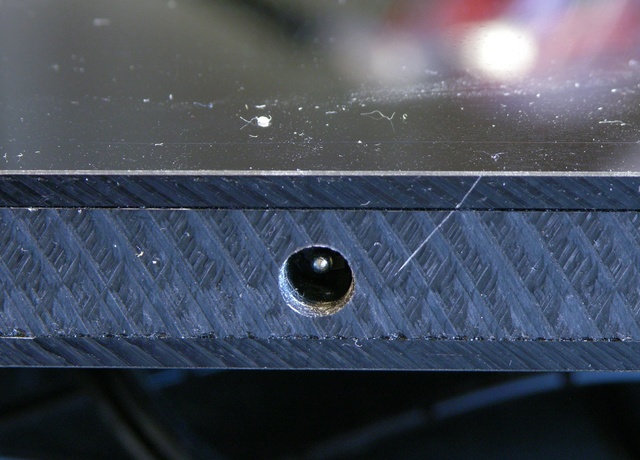
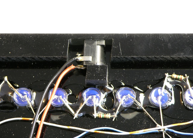
The jack is recessed into the frame. The manufacturer made some effort to get it close to the outside and minimize the amount of recess; but the correct recess for this jack is zero. The plug is designed to make good mechanical contact when it’s sunk completely into the jack; before that point, the springiness of the jack’s outer contact pushes the plug back out of the jack, which is exactly what was happening.
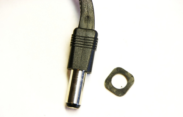
The solution, or I should say hack, was to remove a corresponding amount of rubber from the plug’s molded barrel insulation, so it could once again fit the depth of the jack properly. No further problems.
Dead LEDs
Next I tackled the dead LEDs. A series string of three was dark in the M, leading me to supect one LED burned out and open. Measuring the voltage drop across each, I found the entire ~9V drop across the uppermost LED, so it appeared to be open.
After jumpering across the suspect LED, the other two in the string lit (of course, too brightly relative to their peers), so it was indeed open and the problem.
The right fix would be to replace the broken LED, but I don’t have any white 10mm LEDs on hand, it would take a while to order, frosted 10mm LEDs seem to be more difficult to find (or to find clearly specified as such), and I’d have to wade through long lists of nearly-identical products searching for the one that was actually right.
Immediately I thought of a way I could fix it using materials I had on hand — drill a hole into the back of the 10mm LED and sink a white 5mm LED into it. This idea made me cackle with glee, so you can imagine my disappointment upon realizing I don’t in fact have any white 5mm LEDs here. I need to get me some so I can go back and try that yet. ![]()
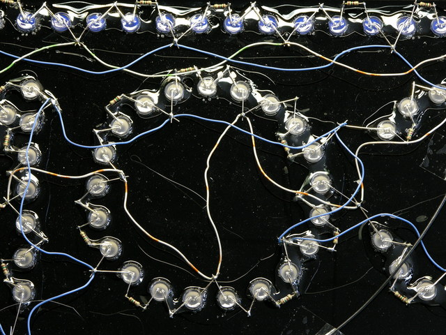
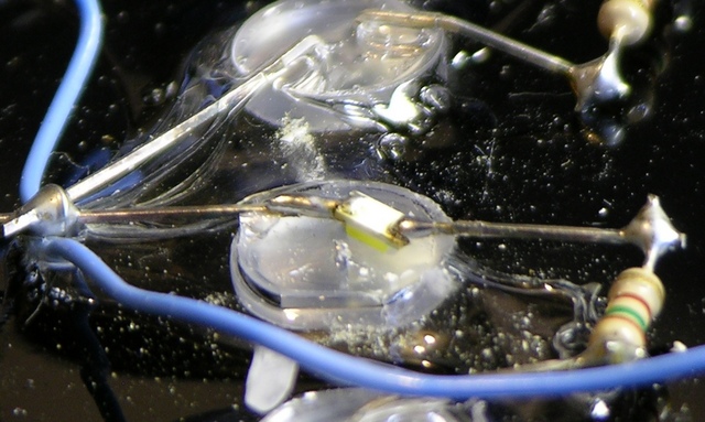
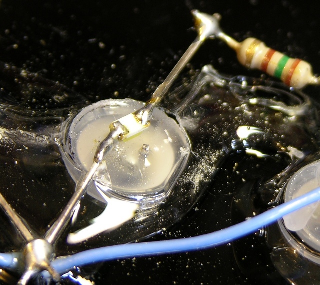
Really, this hack is just as good, though. (Ah, I realize I’m using the word “good” in a perhaps somewhat nontraditional sense.) The SMT LED soldered across the dead 10mm LED’s pins diffused nicely through the 10mm LED lens.
There was also one lonely dark LED in the “E.” Turned out when it failed, it didn’t open, so it was still passing current through for its friends.
I used the same hack on this one, although I did clip one lead off so that the dead LED wouldn’t pull the voltage drop too low for my SMT LED.
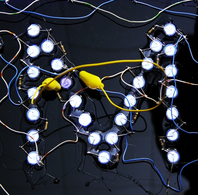
I was surprised at how well the hacked LED in the “M” matched the brightness and color of the other white LEDs, given how different its physical construction is. The one in the “E” is a little more noticeable (picture down below), but probably not objectionable if you’re not specifically looking for it. And I’d say a replacement 10mm LED has fairly good odds of being a little off in color or brightness, too.
At 5mA I should have nothing to worry about; but I watched the first SMT LED with my infrared thermometer for a minute with the power on, and it didn’t get above ambient temperature. Should last a good long time.
“Fixing” the Power Switch
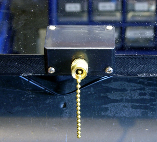
I got the pull-chain switch out of its housing and couldn’t see why it didn’t work. Since my wife said the owner leaves the sign on all the time anyway, I don’t reckon it’s worth replacing the switch, so I removed it and soldered in a bypass wire.
Because the switch was broken in the “on” setting, I could have left it installed and the sign would be on. But the switch is already broken, and who knows when it’ll further break “off” instead of “on.” Under the circumstances, I’d rather bypass it now than have to go back and reopen the case to replace the switch later.
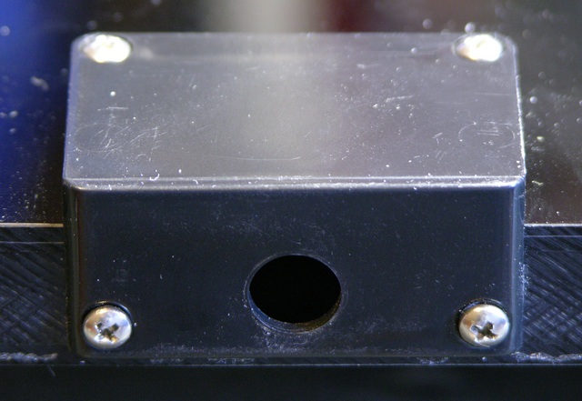
There’s a sizeable cutout in the bottom edge of the back cover for the switch, so it wasn’t really an option to leave the switch cover off. It does look a little odd having the cover on there with no switch protruding, but it’s not awful.
Putting It All Together
And thar she be, in all her working glory. For the moment, anyway.
Shortly after taking that picture, I moved the sign and a couple of blue LEDs on the border went out; then one of them came back on. Half an hour later, both (all) were back on. I’m not sure I’ve seen the end of this yet, and I may have a sizeable job cleaning leads and resoldering cold joints sometime in my future.
Physical Construction
One last thing: the frame and skin construction of the sign forms a rudimentary torsion box. The plastic face and back are quite flimsy by themselves, and even the face with frame glued on was flexing as I was moving it. But the moment I got the back skin screwed on, the entire assembly was quite rigid and immune to flexing and racking. Pretty impressive for such a simple technique.


It’s more interesting on the inside than on the outside. Nice hack with the 5mm leds
Interesting fix. Thanks!
One thing to be aware of is that some white LEDs are based on a UV LED with a white phosphor mix, and some phosphors are subject to early burnout. I have some early white LEDs that are exceptionally dim now due to the phosphor burnout.
As for the construction of the sign, US$300 for a sign of that size/complexity/number of LEDs isn’t all that bad. Blue (and white) LEDs are a bit more expensive than red LEDs, and there are about 250 blue LEDs. So, the LED parts alone may have eaten up a significant portion of that cost, with another chunk taken the by the material and machining for the box, and a bit more for the labour of wiring it up.
As for the wire, stripped network cable is a surprisingly good source for inexpensive hook up wire. I use it quite often. Plus, significant lengths of it are often surplus.
The power supply is definitely a bit wonky, though. That little voltage margin is not a good design, especially given that the mains voltage can vary +/- 10 percent or so under extreme conditions. If it were me designing it, I think I would have went with a bit more head room, even if that had decreased the efficiency a bit. Or, went with a voltage regulator chip. Or, an LED driver chip.
Nice fix on the power connector. I just hope the wall wart never goes bad and needs replacing (since the now non-standard connector will be impossible to duplicate, unless someone knows the trick). As for the switch, I do think I would have plugged the hole, just to keep dust/debris out.
As for intermittent failures, some LEDs seem to have a plating on the leads that is prone to flaking off and/or making bad contact. This was especially true with ancient LEDs. I thought that problem had mostly been fixed with recent production devices. But, without knowing the history/heritage of the particular LEDs, it’s impossible to know.
Also, I’ve thought about building segments, using a similar technique, for a really large 7 segment display. Might yet get to that.
Dave
I love the LED fix wih the SMT devices. Your detailed descriptions of the steps you take and logic of the process make your blog the best of its kind on the net. Thanks!