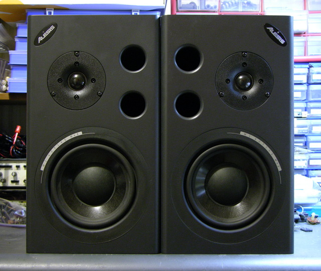
For Friday’s show, we used Alesis monitor speakers that we had in the lab, plus Steve, one of the students, supplied two.
During installation, one of the speakers started winking its blue power light and ceased playing sound, and before the show another did as well. Steve found a Studio Central forum post suggesting that the problem was due to a failed electrolytic capacitor that gets baked by a hot resistor right next to it, and a quick peek inside confirmed that it was a likely explanation and fix.
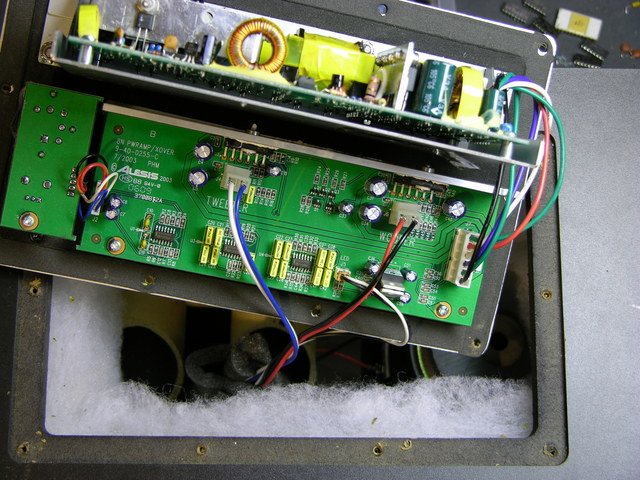
After unscrewing, the back panel lifts out and reveals the power supply board mounted vertically on a metal shield, and the crossover/amplifier board mounted flat on the panel.
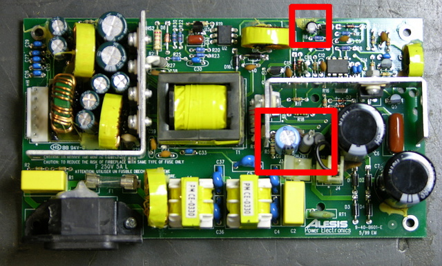
The naughty capacitor, C8 (actually its replacement after I finished), is in the center red rectangle next to the offending resistor. Another bad electrolytic capacitor whose number I forgot to catch is featured near the top of the board. Both of these tested bad with my Capacitor Wizard in-circuit equivalent series resistance (ESR) tester; all of the other electrolytics on the board tested good.
It was simple work to remove and replace the two capacitors on each board, and it brought both speakers back to life. Thank you, forum posts and Capacitor Wizard!
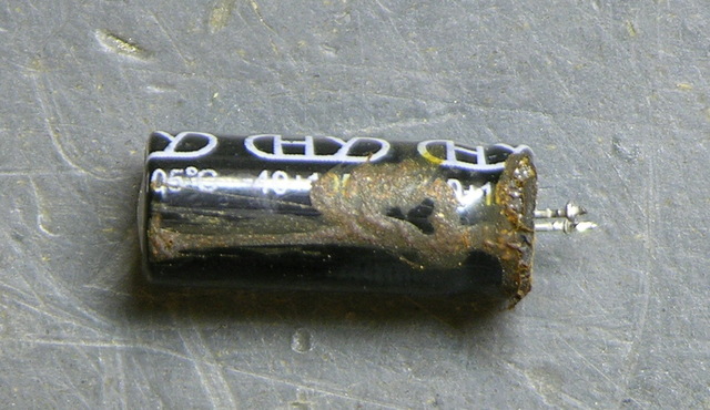
BTW, are electrolytics supposed to look like this?
Two caveats about this repair. First, I should have used 105°C capacitors, but I could only find 85°C caps on short notice, so these will fail quickly and need to be replaced again. At least now it’s known exactly what needs to be done. And second, the forum post suggests moving either the resistor or capacitor to get them further apart, which is a great idea but which I haven’t done yet. I’ve been trying to think up a clever way to stick a little heatsink on a vertically-mounted resistor, which might be a better solution yet.


This is the comment thread that keeps on giving. Just replaced c8 in both my dead monitors and it worked! Thanks everyone for all the information. This is what the ‘net is for.
I fixed the power supply.
https://www.elektroda.pl/rtvforum/viewtopic.php?p=16620577
There are lots of parts to replace:
I did the one replaced both resistors, and c8, and it come back to life, did the same to the other one, but now it doesnt even flicker. What are the most likely things to be gone, because the time I purchase an ESR meter, I could probably replace the most likely components. Are the 4x Diodes D1-D4 likely to be at fault here?, as Ive tried reading them and they are coming back around 800 mark, but they are in circuit. So Im stuck at the minute what to do next? Maybe the pair of large Caps.
I have a problem with one of these. The C8 cap had died and taken out the oscillator and FET transistor, there was also a bulge on one of the main caps after the bridge. The PSU just pulses about 1Hz, if I hook it up to the rest of the speaker it’s like you’re just switching it on and off continually. Voltages look OK and I’ve not been able to find any duff components, I’ve been using the other speaker to reference it. Can’t see what’s wrong with it, beginning to get frustrated. Any help would be awesome.
So the pair I have have been powered for the last couple of years only being turned off for the week we were away on vacation.
When I returned and turned them on one let out a “FIIT” and a “POP” with no sound or light. I pulled the plate and had a look at the PS. The caps actually looked good and there was no signs of over heating on any parts. Close inspection of the board and specifically the switching chip showed a small hole in the top. AH HA!
I look up the chip and see that they bought cheap knock offs of the ST UC3845B. While I am at it I notice that one of the PS input caps is oh so little bulging at the top. So I ordered up rated parts from Digikey as well as the actual ST devices. While I was at it I also bought the cap to replace the 330uF 35V unit as well.
A note, the parts are not much more for 10 PCS than the required one or two of each so I bought 10 of each part. Total cost for the lot was less than $65.00 USD to my door.
30 minutes of swapping parts and all together again. Switch it on and all is good!
Funny thing. Went away for a week and returned. Turned on the speakers again and the other one crapped out!!! Lucky I had the parts on hand. Another hour and I was up an running again.
Not happy with the fact though that they are so cheap on the PS and the rating is only really 30W of output. This means that the actual sustained output of the speakers is likely to the south of 20W.
Think the next thing will be to upgrade the PS with a toroidal transformer, bridge rectifier, caps, and regulator board os I can dump the switcher all together. Hell they work and they are expensive. They will more than pay for the parts to upgrade to a good proper supply. I will Ebay them!
good guide. @Matthew I think we’ve got the same issue: while power on I have LED and speaker pulses at about 1Hz. There were two heavily burnt caps: C28 and C29 (the small ones in the corner). I’ve replaced them but still got the 1Hz pulses.
I’m looking for switching power supply repair info, especially for this “on-off-symptom”.
I’ll post news here.
Hello, I’m a newbie trying to determine if my MK2 problem can be helped by this thread. One of my speakers works just fine at low-ish volume. The blue LED flickers ever so subtly though, and at higher volumes, the woofer will cut out or clip intermittently. Soldering is beyond my skillset, but I know some people, I’d just like to point them in the right direction or at least be able to advise a potential buyer. Any guidance would be greatly appreciated.
Hey! There’s no easy way to tell without giving it try, but the LED flickering is a sign for sure.
That was one of the symptoms that my speakers developed before the died totally. I also has a very low frequency pulse happening in time with the led, which also pointed to the bad cap. The repair is pretty easy for someone with a mid level of experience and took me about 15 min total. I’m an occasional hobbyist solderer with crappy equipment and it was very easy for me. A pro or mid level amateur should have no trouble. Good luck!
Riik,
So looking at the crossover/amp board, this is where the LED comes off of, it is across the pair of linear regulators used to supply the crossover section. In this case they are a pair of positive (7815) and negative (7915) 15VDC units. Flickering indicates that one or both of the feeds from the power supply are sagging in output.
A note, it could be one of the 7×15 regulators but I doubt this as they are pretty reliable when not pushed. These are pretty crappy supplies and are well known for the caps being an issue so there is where I would be looking for starters.
So I would be willing to bet that the issues are due to bad caps sincethe supplies still seem to kinda work. The parts I would have on hand for the soldering mavens would be at least 4 pcs of 390uF, 200VDC At least 105C or higher rating!!! (C6 and C7) These are the input caps on the line side of the power supply. The other one is close to a pair of power resistors close to the power switch connector. The resistor is R4. You will need a pair of these and the cap is a single 220uF, 35VDC unit. Again at a minimum this should be a 105C rated cap.
For the inputs (390uF) I bought Rubycon parts and the switching regulator power cap (220uF) I bought Panasonic. These were both from Digikey so the likelihood of them being counterfeit is small. I would not recommend buying electrolytic off of Ebay if it can be helped, especially from China unless you are familiar with the seller which I suspect you would not be.
Hope this helps.
Mike
Hi, Cleveland king.
The value of R27 is 0.02 ohm 1Wtt
Hi, This thread is amazing.
Recently picked up a pair of these speakers for a bargain. One is not working, seems like the infamous RT1 part and R3 are gone.
I’m having trouble finding the replacement for
R3
RES 47K OHM 2W 5% MO CFR-VM. As specified in the service manual.
Specifically the MO CFR-VM is confusing me as I am not electronically literate but its an easy solder to fix.
Can anyone link me to the replacement part, preferably in Aus!
Cheers.
So, my problem does not involve a blinking blue light, but no light at all. A swift smack to the top of the speaker brings it back to life. Does anyone have any ideas on a cause or fix to this issue? Any help will be greatly appreciated.
Thank you.
This site has been very useful, though I had to give up on repairing the PSU after having spent days to get it working in a stable way. It seems the power supply is unstable at low temperatures – the duty cycle of the main switch is at 50% or <1% alternating switch-cycles. The active clamp can't deal with the low duty cycle and the power supply has high loss while the output voltage is around 30V. After it's been heated up, power cycling will restore the supply to stable operation at around 30% duty cycle.
I've replaced all semiconductors and electrolytics. I've experimented with different values for R18 (this varies between units anyway) – higher values seem to reduce the likelyhood of the psu snapping into the unstable operating state at startup. After a while the power supply seems to work, but that it only because it has heated itself up enough. Using freeze spray on the heatsink and watching the Q1 drain waveform on the scope, the power supply will start up unstable at lower temperatures, and the unstability doesn't resolve untill power is cycled. Has anyone seen this phenomenon and found a solution?
My MI blew a fuse , Q1,3,4 and R11,D9,c15 with it , a new board is
140USD, is it worth it to manually repair and wat other components should be replaced , like all the electrolytics and ICs?
I rebuilt the power supply board after about 4 components had exploded, I replaced over 20 components , on bench test fuse blew , I give up ! My only choice is to make a custom power supply , can anyone tell me the voltages on the input plug , I do have a schematic . I’ll need to know current demand also .the replacement board is no longer available.
Hi,
I was wondering if it is possible, as I cannot get a replacement power unit for one of my speakers. To make them passive, so I can use any other amplifier.
Many thanks
Aaron
I did this to a pair of mine as I gave up trying to fix the power supplies. I removed all the electronics from the units to leave just the two drivers. I fitted a 2-way crossover and some banana-plug connections so they were just passive monitors and ran them with an external amplifier as per regular speakers. I had to do a bit of drilling to add in stand-offs to mount the crossover and for holes to add in the banana-plug sockets, Then solder the speaker terminals to the input of the crossover and then to the drivers.
Worked a treat and TBH sounded much better than it did originally.
Thanks man. Seems straightforward enough. I will do it and let you know how I get on.
Hi-
My left Alesis M1 Active mk2 speaker no longer powers on. The right one is fine.
Is anyone here interested in purchasing either or both?
Thanks!
-Susan
Where are you located Susan?
Sorry for the late reply, Aaron. We’re in New York State (Putnam County)
Hi Matthew
Just wanted to say thanks, I followed your advice and successfully made them passive speakers today. Very happy and cost probably just a bit more than one of the power units. Also think they sound so good. Probably better than the mk3 I got to replace these.
My blue light was intermittent and then suddenly there was a crackle and smoke came out of one of the bass holes. Quite a lot of smoke!
My resistor R11 was destroyed (Anyone know what value it is?) and the two black 3 legged components (transistors maybe?, 2N 4401? ) also have one leg eaten away. There was soot all around R11 which had basically disintegrated.
There is no physical sign of damage on the capacitors.
Unsure what to do now.
Well you have a second unit so you have a functioning reference to look at and take measurements from which to compare. That is where I would start.
I don’t know if it’s the case with Keith’s MK2s, but R2/3 ran so hot in mine that on top of cooking C8 dry, they darkened the circuit board (visible from the underside of the board) and melted a hole into the batting in the speaker cabinet. I’ve posted a few photos of this at Maker Pro:
https://maker.pro/forums/threads/the-alesis-m1-active-mk2-problem-capacitors-dying-from-resistors.296898/post-1843403
At minimum, if the PSU is repaired by replacing C8, it should also be re-housed in a ventilated/heat-sinking enclosure and mounted on the exterior of the rear of the speaker. It’s very easy to run the cable between the PSU and the amplifier/crossover board through the hole for the kettle lead, and the PSU board’s mounting plate is held to the speaker’s rear panel with bolts, so that whole assembly can be removed into whatever new housing you choose. No excessive modification of the speaker body is necessary, just ensure the kettle lead port and power switch port are covered with something rigid and sealed to prevent pressure leaks.
Info for anyone looking to repair them by fully replacing the PSUs, or by turning the speakers into passives:
Alesis M1 Active MK2
Woofer: 75w, 8 ohm
Tweeter: 25w, 4 ohm
Crossover: 2kHz
“Specifically in the case of the M1 Active Mk2, the wide, mid-frequency
polar response of the tweeter can be utilized down to a low 2000 Hz
thereby mating more cohesively with the 6.5″ non-woven carbon fiber
(NWCF) woofer. This low crossover point is only possible through the use
of a steep, electronic fourth-order (24 dB per octave rolloff) high pass filter.”
Tweeter PSU output: 18V
Woofer PSU output: 36V
Tweeter amplifier: LM2876
Datasheet: https://www.ti.com/lit/ds/symlink/lm2876.pdf
Woofer amplifier: LM3886
Datasheet: https://www.ti.com/lit/ds/symlink/lm3886.pdf
PSU cable output to crossover/amp board:
-V_LO (green)
+V_LO (red)
AMP_GND (white)
SIG_GND (blue)
-V_HI (green)
+V_HI (black)
Don’t turn them off!
So an update on the speakers. They have been working for the last 5 years only being shut off for one week a year over the last 5 years. The other day I turned them off only to have them not come back on when I turned them on a few days later.
When I originally effected the repairs I did replace the cheap caps with much better units that were higher spec and better temp ratings. I replaced the resistor that was running hot and extended it further off board and away from the caps. I also had to replace the switching regulator at the time and used the real device rather than the cheap no name crossover chip that was in them originally. I seldom drive the speakers hard so heat should not have been an issue.
I think I am going to be replacing the troublesome, and WAY UNDERSIZED switchers in the box with a 300W torroidal and a pair of linear regulators for each of the amp pairs. Feed to be brought in via the EIC connector port that I will replace with a blank and Anderson power pole connectors sealed up with silicon. I will use the power switch to simply control the mute circuit. the supply will be replaced with a board with large filter caps fed from the external supply. That should remove the vast majority of heat and provide far more headroom too. I may fix the supplies and simply sell them but what a pain in the ass.
Thanks for the information. One of mine just went out last week and really didn’t want to buy new speakers. One of the large black caps was bulging on mine so I replaced one of those as well. Might go back through it and replace the other one and also do the other speaker for peace of mind. But it’s working great now thanks to the info here.
Well finally got around to ordering in a few parts for the repair of the speakers. This time I had to replace a driver transistor, one of the 2n4403 as well as the MOSfets. In one of the speakers one of the mosfets was bad as was the driver. While I had the heat sink out I simply replaced both since they are cheap and it was easy. I also took the time to replace the crap silipads with Mica and Arctic MX-2 compound. The insulating washers were baked as well and I had some that were far more stout than stock so those got replaced as well. The other one had both mosfets smoked and took out a couple of the 2N4007 diodes on the power input so I replaced all four. I replaced the 2N4403 even though it was good since they are pennies and the same device had died on the other speaker. Replaced the mosfets and used mica and MX-2 compound as well. The silipads had failed and shorted them to the heatsink. Did I mention that I hate silipads and that they don’t belong anywhere other than a land fill.
I have most of the parts required for the replacement of the power supplies with an external 300W linear upon the next failure. Just waiting on the connectors and the wire for the umbilical cords. A single 300W toroid with separate dual 15V and 28V windings is right on the money after full wave rectification. Gonna due dual mono after the transformer and give each pair their own DC rectifiers and cap banks. I will put woofer and tweeter cap banks in each speaker in place of the power supply boards to feed the amp board. Kinda done with these total crap switchers after having to repair them for second time.