Older Arduino boards like mine have two annoyances associated with uploading software to them. First, you have to press the reset button (physically) to trigger the bootloader to expect new software from the host computer. Second, the Arduino waits allegedly 6-8 seconds (actually about 10 on mine) on every boot before starting your program, in case you might want to be uploading new software to it.
Small annoyances, to be sure, but they add up quickly when you’re trying to tweak a timing constant in a program and uploading software repeatedly. Thus in designing the latest Arduino, the Diecimila, the team addressed these two issues.
On the Diecimila board, they added a capacitor between the USB-serial chip’s DTR line (active-low) and the microcontroller’s reset line, so that the host computer can trigger DTR and pull down the reset for a moment, relieving you of pressing the button. In the new version (10) of the IDE, they added code to support that new functionality. And in the bootloader burned into the ATmega168 microcontroller, they shortened the boot wait time to a second or less.
All of that comes prepackaged for Diecimila owners; but owners of older Arduinos are resourceful and found how to adapt their own boards as well. The NG can be hacked by soldering a capacitor across two adjacent pads that appear to have been put there for that purpose. The Arduino serial can be hacked by stringing a capacitor between the serial connector and the reset line.
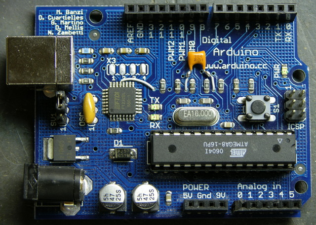
But I have an Arduino USB, the first version to support USB and not yet a “next generation,” and I haven’t been able to find instructions on modifying it. It doesn’t have the pads already broken out like the NG; in fact, it doesn’t even have the same package USB-serial chip. So I muddled through, found the right pins, and did it myself. Works (mostly) great!
Finding the Right Pins
The page for the NG hack simply shows you physically where to put the capacitor on the NG board and doesn’t describe what it’s connecting electrically, which didn’t help me, as I needed to figure out where to put it on the physically different USB board. Fortunately, the page for the Arduino serial hack gives the critical information:
The retrofitting process consists on soldering a 0.1uF disc capacitor between the DTR pin [of the serial port or USB-serial chip] and the Reset signal [of the microcontroller].
Good enough!
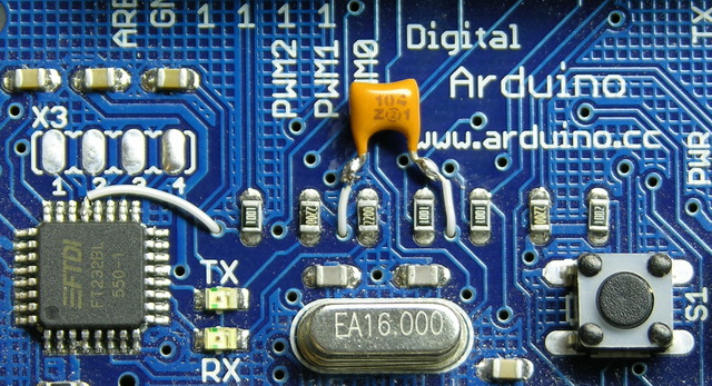
I got the datasheet for the FTDI FT232BL USB-serial chip, and for a moment got my hopes up higher than I should have. The DTR line is in the row toward the top of the Arduino board, and it looked as though it might already be broken out into the unpopulated, .1″-spacing X3 header. Nope, nope, it’s about the only line on that side that’s not already broken out. I was going to have to solder directly to the chip.
Given that it’s a 7mm-square LQFP with .8mm (.03″) lead spacing, I should perhaps have set it out with a thimbleful of Special Sheep Liniment to entice the Nac Mac Feegle to solder for me. But I have no dearth of hubris, and soldered it myself. Twice, in fact, the second time after cutting the other end of the wire too short to reach the capacitor.
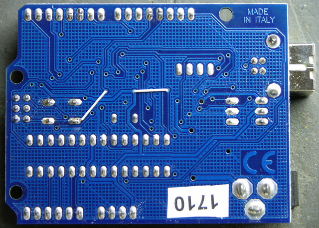
One side of the capacitor connects to the DTR line of the USB-serial chip, the fourth pin from the left on the upper edge. The other side connects to the reset line, which appears to be available only on the microprocessor, the ISP header, and the reset button. I chose the reset button on the underside of the board.
I could have used a capacitor with long leads, sleeved them, and connected them directly to the pins at both ends as in the serial board hack; but I thought it looked better to use wire-wrap wire.
I laced the (insulated) wire-wrap wire through open vias in the board to keep things tidy and the capacitor snugged down. A few dots of glue would have done the same had I wanted to keep all the wires top-side, but this felt a little more artful to me. Plus it seemed easier to solder to the underside of the reset switch rather than the top, so I was feeding a wire to the back side of the board anyway.
IDE and Auto-Reset
I upgraded the integrated development environment to version 10, which adds the DTR-triggering, and tried it out. The host computer does indeed now reset the Arduino, and I can upload software to it without pressing the button! Hooray!
But there’s still about a 10-second delay after a boot, reset, or upload before the software starts running. Boooo!
Bootloader and USBtinyISP
One of the hacking guides suggested that the Arduino bootloader would need to be upgraded in order to reduce the reset delay, which makes sense. The IDE includes the ability to burn a new bootloader, for which the bootloader web page gives instructions. Burning the bootloader, unfortunately, can’t be done through the Arduino’s serial interface; it requires a separate AVR programmer.
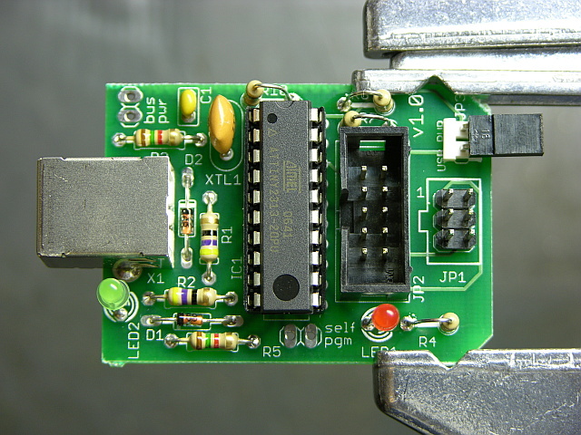
Thus it was time to assemble my USBtinyISP kit from LadyAda.
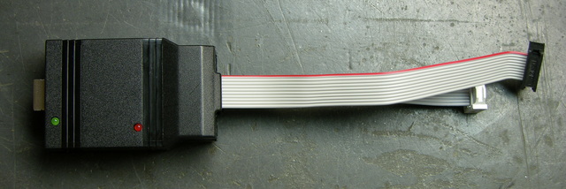
I bought it a while back in order to be prepared for programming ATmegas outside of the Arduino board. It’s an Atmel ATtiny chip interfacing directly between a USB connector and two cables for in-system programming. The board is nicely made, the instructions are clear enough for absolute beginners, and it was a joy to solder.
Fully assembled, it lives in a shell that makes me think of old serial line drivers; but the shell is somewhat customized to fit the USBtinyISP board (and vice-versa).
I read recently and have since forgotten the name of the little “columns” built into plastic enclosures (like toys) to hold PCBs in place; but no matter, since my point is that this case doesn’t have them. The USB end of the board had a lot of room to move and was a bit wibbly-wobbly, but I took the foam that the chip shipped in and packed it between the USB connector and the top of the case, which secured the whole thing nicely.
The term is mounting bosses, seen at Near Future Laboratory.
That done, I unplugged the Arduino’s USB connector, plugged the USBtinyISP into the Arduino’s ISP header and into my iBook’s USB, and burned a new bootloader. I went to the Arduino IDE’s Tools / Board menu and selected Arduino NG or older w/ ATmeta8, then Tools / Burn Bootloader / w/ USBtinyISP. The USBtinyISP’s programming light went on and IDE told me it was burning and would take a minute. Twiddle twiddle.
Finished. Disconnected the USBtinyISP and reconnected the Arduino. It didn’t seem to have my program on it any more, which I guess makes sense that doing low-level AVR programming would wipe the whole memory. I uploaded my code again; and when the upload finished, it took about 10 seconds to start the code. Hrm. Pressed reset, and it took about 10 seconds. HRM.
Arduino Bootloaders and ATmega8
My Arduino is so old that it has the ATmega8 instead of the ATmega168. I don’t know whether that’s true of all Arduino USB boards, but it’s certainly true of mine.
It would appear that the ATmega8 bootloader image has not been updated for the auto-reset. Poo.
The bootloader source code is available online, but the ATmega8 code looks unusable. By that I mean that large sections of code are commented out, including the part that makes timeout after n seconds. (Yes, I’m saying it appears that it would wait forever for a software upload before starting your program.)
It looks to me like it’s been half-***ed patched with updates that have been made to the ATmega168 bootloader, but that parts that would have taken any effort to fix have been commented out rather than updated. Yes, I’m bitter.
See the comment from David Mellis, a developer of the Arduino, below. The timeout value is still present; I just didn’t look carefully enough. The ATmega8 bootloader code probably is what’s in the IDE, and it should be possible to recompile it with a shorter timeout. I’ll provide a further update once I get that worked out.
Interestingly, the ATmega168 bootloader code includes conditional compilation for many different ATmega chips, including the ATmega8. It seems likely that I could build it for the ATmega8 and get it to work. However, the bootloader web page says that the ATmega8 bootloader is only 1k rather than the newer bootloader’s 2k, an important savings given the ATmega8′s mere 8k of FLASH.
Fix the abandoned ATmega8 bootloader code myself? Sacrifice an extra 1k of program space by using the newer bootloader? Sigh.
Another option would be to buy Lady Ada’s preprogrammed ATmeta168 microcontroller. Of course I’d check first, but I think the ATmega8 and ATmega168 are pin-compatible. If that’s the case, I could pop in a 168 (preprogrammed from her, or straight from the factory and program it myself with the USBtinyISP) and be done with this. But it really grates on me to replace hardware when a software fix is perfectly viable.
And of course I could just try lying to my IDE about what chip I have and burning the ATmega168 bootloader into my ATmega8. But looking at the source code, there are enough differences between the ATmega168 and ATmega8 sections that I’m leery of doing this. I wouldn’t mind if it simply didn’t work, but I don’t know enough to be sure it wouldn’t damage the chip somehow. I’d rather live with the delay (for now) than destroy the only chip I have (for now).
To Sum Up
The capacitor-reset hack was easily adapted to the Arduino USB, if you don’t mind a little fine-pitch soldering. Yay! That plus an upgrade to v10 of the Arduino IDE allow the host computer to reset the Arduino when uploading new software, relieving you of pressing the reset button each time. Yay! But I don’t yet have a solution to reduce the reset delay on a board using the ATmega8 microcontroller. Boo!
Actually, the ATmega8 bootloader source code that you linked to (also included with the IDE) should be the one that was burned onto the ATmega8′s that shipped with the boards. The timeout is in fact enabled, just hidden inside the getch() function. You should be able to simply change the value of MAX_TIME_COUNT and recompile. You might need to find the right version of avr-gcc to keep the code under 1024 bytes. I think I’ve had luck with 4.0.2.
Also, yes, you can just replace the ATmega8 with an ATmega168.
Oh, and, also, great article!