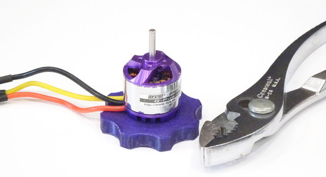
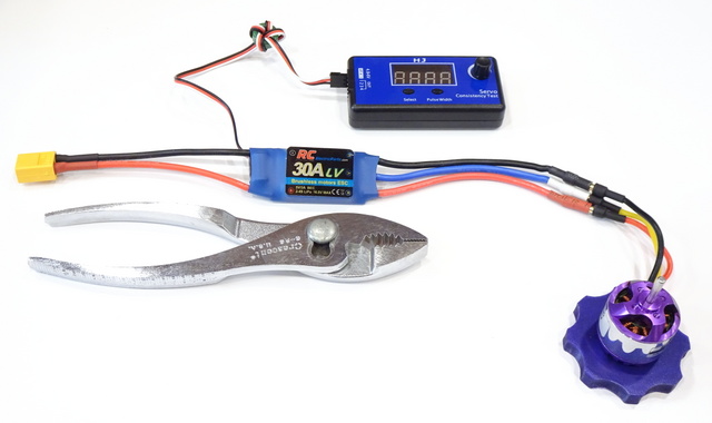
I had not worked with hobby BLDC motors before (I keep saying “hobby” here because my cordless drill and driver have BLDC motors); but as you can see, they’re cute as the dickens. Much cuter than chickens. About walnut-sized, and very cheerful. More cheerful than chickens?
YouTuber How To Mechatronics has a stellar video How Brushless Motor and ESC Work and How To Control them using Arduino explaining all the theoretical and operational details of BLDC motors and their electronic speed controllers (ESCs). If you want to know (pretty much) everything about them, go watch! Or for a quick overview, keep reading.
BLDC motors resemble steppers in that they have coils that must be energized in sequence to move the rotor. Unlike (typical) steppers, hobby BLDC motors have three (sets of) coils with a common node connecting one end of each coil (set of coils). Passing current in sequence through two at a time of the three wires energizes:
- V+ → A coil forward → common → B coil reverse → V-
- V+ → B coil forward → common → C coil reverse → V-
- V+ → C coil forward → common → A coil reverse → V-
with the effect of using one coil (set of coils) to pull the rotor’s permanent magnet(s) toward it/them and another coil (set of coils) to push the rotor magnet(s) away.
And the unused wire during each step is used to sense back EMF, to close the feedback loop for managing acceleration. Slick!
Such an arrangement requires a driver; and because these motors are targeted at (RC) hobby use, the BLDC drivers (electronic speed controllers) are commoditized, configurable, and convenient. The ESC has an XT-60 LiPo battery plug for power, bullet connectors to feed the motor … and a servo input for control.
That’s right — you inform the ESC what speed you want by feeding it a servo control signal, with short pulses being interpreted as off and longer pulses being interpreted as faster. Moreover, the user guide for my ESC describes what I gather is a common process of powering up the ESC with the servo signal at max, waiting for the ESC to beep (by sending audio-frequency signals to the motor, using it as a speaker), and turning the servo signal to min to calibrate the ESC’s expectations for this particular servo signal transmitter’s range of pulse lengths. That’s only one of many parameters configurable through the simple servo control interface; it’s really well thought-out.
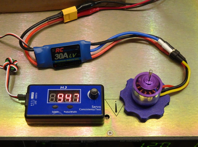
The only things left were power — the rackmount power supply it’s sitting on — and a servo control signal. Younger me with more free time would have programmed an Arduino; but recent me bought a servo tester, which even displays the (alleged) pulse width in μs. Patched together, the knob controls the motor speed and with the addition of a 3D-printed base, I can test the motor!
Worth noting is that the visible housing is part of the rotor — the stator coils surround the axle and the permanent magnets are affixed to the inside of the housing. That’s disconcerting to handle and is the reason for the grippable base.
One more note: Hobby BLDC motors have a “Kv” rating representing the maximum rpm per volt of the power supply. The same size package could have more turns of fine wire for lower current and higher torque or fewer turns of coarse wire for higher current and higher speed, given the same load. Rotor Drone Pro has a nice overview of Kv and motor and propellor selection for aircraft.
Expenses
Everything was about the cheapest I could find on Amazon:
- 850 Kv BLDC motor: $14.99
- ESC: $16.49
- servo tester: $11.99


