Over the holiday break, I had written about using a hairdryer to heat my CupCake build chamber.
On January 11, 2010, Tom McGuire wrote:
Hey Keith, I haven’t caught up with your blog for some time. Looks like you got a lot done in the last couple weeks. It’s good to see you’re getting results from your CupCake.
Can I help you with a hot plate? I could make you a thin aluminum plate about 4″ square that gets up to 200°C. I guess you would need it to be insulated on the bottom to keep from burning your stage. Do you have a low voltage with lots of current available, say 12V @ 10A or may be 5V @ 20A. What do you think?
What did I think??? I thought it sounded great! The heated chamber was helping my prints, but I was still getting some warp. I knew a heated platform was the way to go and it had been my goal all along.
We started discussing the way other folks were making their heated platforms and Tom went on to say:
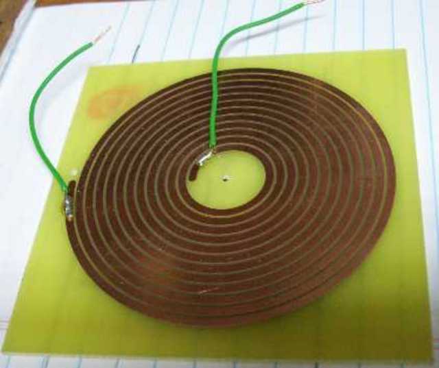
Oh 100°C would be no problem for PC board material. I was thinking at first to place a bunch of low ohm surface mount resistors around on a 4″ square PC board but then I remember we did this other project that was supposed to be in inductive coil for an induction heating system. It turned out to be more of a heater coil itself. I could do something like this but in a square pattern and leave openings for your screws and magnets.
Because I wasn’t sure yet whether the heater PCB would mount fairly directly to the Y stage (and thus need holes for screws and magnets) or be raised above it (far enough that it wouldn’t need holes), I pointed Tom at the CupCake CAD files on Thingiverse.
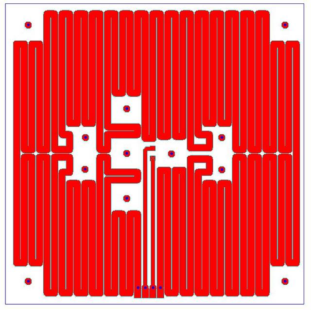
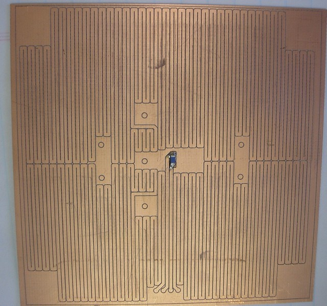
He downloaded the DXF for the original build platform to get the hole size and spacing, then laid out this heater PCB with traces fitting around all the necessary openings.
Then he showed up for lunch with a milled heater PCB that ended up measuring 4Ω resistance (an extremely convenient value) and with an SMT thermistor already soldered in the middle.


Very nice! I also made a heated platform from PCB material because it can withstand and distribute the heat but I wouldn’t have though to use the copper itself as a heating element. Your solution is much more elegant.
http://www.flickr.com/photos/28172221@N08/sets/72157623375295929/
What are the two interior pathways for?
Jay, if you’re referring to the two inner traces on the four-pad breakout for TBD connector, those go to the SMT thermistor in the middle of the PCB.
Maybe you could also use vero board? It already has lots of parallel tracks – just link them at the ends. Of course would probably have to combine a couple on a substrate to get the right size.
PCB files worth sharing?
D.
Darkith, the PCB files aren’t worth sharing yet. We’re going to move the connector outside the footprint of the aluminum plate on v2, which will be a significant improvement.
Wow amazing! I am looking to build a heated bed like yours but for the mendel with the Gen 4 electronics. Any idea of how to build a good one for the mendel?
Thanks!
Mark Fuller
Hi,
Can you tell which value, or model you are using for the SMT thermistor ?
Thanks.
Didier, it’s the thermistor that came with the CupCake batch 1 kit. I’m not certain what that is, but it’s probably in the parts list on the MakerBot wiki?
Didier, I apologize; I understood your question when you asked it and then forgot by the time I answered.
I also don’t know what the thermistor on my hotplate is — Tom McGuire had provided and soldered it and I never found out. I need to know so I can determine the beta without submerging my whole plate in water — although I probably should have done that when I first received it. Meanwhile, I’m running without closed-loop feedback, which is less than ideal.