I’ve put off working on my LED calculator project for far too long, at first trying to find the right handheld case to put it in and then later hoping to be able to manufacture a case myself. I’m not having any luck with that right now and if I keep waiting I’ll wait forever; so I’m resurrecting the project with the intention of selling it as a kit sans case.
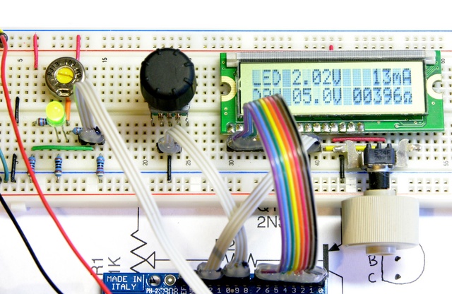
The idea is to expand on a simple LED tester by allowing the user to plug in an LED, dial in the LED brightness, and then read information on an LCD showing the LED voltage drop, the current current, and the value of current-limiting resistor to use in a target circuit.
A microcontroller determines this information by measuring the voltage drop across a series current-sense resistor to calculate the current and measuring the voltage drop across the LED to calculate how much voltage will drop across the current-limiting resistor in the target circuit and what that resistor value should be.
Variable Resistor Drive
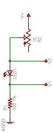
Until now, all of my prototyping has used a variable resistor in series with the LED to set the current. After subtracting the LED’s forward voltage drop from the supply voltage, the variable resistor dominates the resistance of the remaining series chain (which includes the current-sense resistor), thereby setting the series current.
This does give control over the LED current and brightness, but the problems with this method are:
- A small-valued potentiometer doesn’t provide enough resistance to dial down to low enough LED currents. For example, a 1K pot with the circuit running on 9V won’t deliver less than 6mA, depending on the LED color (and voltage drop); and modern, high-efficiency LEDs are surprisingly bright at 6mA.
- A large-valued potentiometer has an extremely non-linear current response, with all the “action” at the very end of its rotation.
Here’s the response of two different LEDs with a 10K potentiometer:
| Position | Green LED Current | Blue LED Current |
|---|---|---|
| 0 | 1mA | 1mA |
| 1 | 1mA | 1mA |
| 2 | 1mA | 1mA |
| 3 | 1mA | 1mA |
| 4 | 1mA | 1mA |
| 5 | 2mA | 2mA |
| 6 | 3mA | 2mA |
| 7 | 4mA | 3mA |
| 8 | 5mA | 6mA |
| 9 | 34mA | 21mA |
| 10 | 100mA | 89mA |
Very slow response until near the end of the potentiometer’s rotation, at which point the response is so rapid that it’s very difficult to control
And of course this makes sense, as it’s the hyperbolic curve of I = V/R.
Transistor Drive
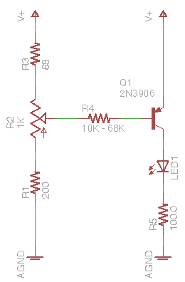
Last week I started looking at improving the range and linearity of the LED current. I’m not looking for a perfectly flat response curve nor for a true constant-current drive; I just want a somewhat better response. What came to mind was this simple PNP transistor circuit — actually an even simpler version without R1 and R3, but I’ll explain their purposes in a bit.
The theory is that R2 (or R1 + R2 + R3) acts as a voltage divider across the power supply, linearly setting a drive voltage. R4 (nearly) linearly turns this voltage into a current sink across the PNP transistor’s emitter-base junction; and because R4 >> R2, R2 presents a “stiff” voltage source to R4, meaning we can largely ignore R4′s effects on the voltage division.
Thus R2 provides (nearly) linear control of the emitter-base current. In the common-emitter configuration, the PNP transistor amplifies the current by the transistor’s β (about 150-200 for a small, general-purpose PNP like the 3906) for a correspondingly higher emitter-collector current
IEC = β IEB
which goes through the LED and the sense resistor, providing (nearly) linear control of the LED brightness by turning R2.
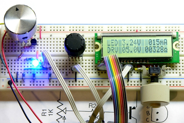
Well, that’s the theory, anyway. This weekend I dug out the prototype and built up the transistor control to test it in practice.
(70s decor courtesy Radio Shack.)
The first thing I noticed was a section at the CCW end of R2′s travel in which nothing happened, because R2 wasn’t providing more than the transistor’s cut-in voltage — that is, although VB was less than VE, it wasn’t enough less to overcome to emitter-base forward voltage drop and bias the transistor down into the active region.
I tried installing a small-signal diode “above” the potentiometer so that VB would always be at least .6V below VE and eliminate R2′s dead region, but the diode’s forward voltage drop was a little too high (it did too good a job) and the resulting minimum LED current was a little higher than I liked. I settled on adding R3 in that position, selecting 68Ω as a value that worked well with both traditional and high-power / high-efficiency LEDs and with both 9V and 7.2V supplies.
With a 9V supply and R3 = 68Ω, I tried three different values of the base resistor R4.
| R2 Position | R4 = 10kΩ | R4 = 22kΩ | R4 = 47kΩ | |||
|---|---|---|---|---|---|---|
| Green | Blue | Green | Blue | Green | Blue | |
| 7:00 | 0mA | 0mA | 0mA | 0mA | 0mA | 0mA |
| 8:00 | 0mA | 0mA | 0mA | 0mA | 0mA | 0mA |
| 9:00 | 8mA | 7mA | 3mA | 2mA | 1mA | 1mA |
| 10:00 | 30mA | 30mA | 15mA | 13mA | 7mA | 6mA |
| 11:00 | 46mA | 42mA | 24mA | 22mA | 13mA | 11mA |
| 12:00 | 56mA | 47mA | 34mA | 32mA | 17mA | 17mA |
| 1:00 | 60mA | 48mA | 42mA | 40mA | 24mA | 22mA |
| 2:00 | 62mA | 49mA | 49mA | 44mA | 29mA | 26mA |
| 3:00 | 62mA | 49mA | 53mA | 46mA | 32mA | 30mA |
| 4:00 | 63mA | 49mA | 55mA | 47mA | 34mA | 31mA |
| 5:00 | 63mA | 49mA | 55mA | 47mA | 34mA | 32mA |
The table shows a similar effect at the other end of R2′s travel in which the LED current was pretty well maxed out and not increasing any further. I think I was hitting the knee between the transistor’s linear region and saturation, meaning increasing IEB was no longer increasing IEC. Experimentation gave me R1 of 200Ω keeps the transistor pretty well out of saturation and gives a satisfyingly more-linear response than what I measured here.
The 0mA readings at the beginning of the table, by the way, are a bit deceptive — some of my test LEDs are actually lit in that region. I’ve updated the Arduino code to show tenths of a milliamp when the reading is below 10mA, and I can see LEDs glowing with as little as .1mA. Probably not a value of interest for most people, but it could be effective for making flickering gas lamps for model railroads.
Choosing Values
R4 = 22kΩ looks like a pretty good compromise between providing a near-linear response and covering the range of LED currents I expect most people would be interested in testing, so I’ve tentatively settled on it.
I’m still fiddling with values to give good performance at both 9V (alkaline battery) and 7.2V (NiMH), because I use rechargeables almost exclusively and want to make this work well on rechargeables to encourage other people to do the same. The problem is,
Vsupply = 7.2V
VEC ≈ .8V
Vblue LED ≈ 3.5VVR5 = Vsupply – VEC – VLED = 7.2V – .8V – 3.5V = 2.9V
ILED = IR5 = VR5 / R5 = 2.9V / 100Ω = 29mA
In other words, running on a 7.2V battery, with the transistor saturated, a blue LED with a 3.5V forward drop maxes out at 29mA; and it gets worse with a battery that’s not straight out of the charger and some white LEDs with a higher forward voltage drop. I’d like to enable people to test up to 50mA, to cover high-brightness LEDs, so I’d like to push this maximum current a little higher.
R5 = 68Ω gives ILED up to about 42mA, which isn’t as high as I like; but the tradeoff is that a smaller R5 gives me a smaller voltage range to sample in the A/D converter, hence lower resolution for the display. 68Ω seems like a good compromise. And I’m already thinking about a DPDT switch to change the resistor and alert the microcontroller about battery chemistry.


There is just one problem with the project. It has no rotary encoder!
Au contraire, Anton! The rotary encoder is still there to set the voltage of the target system for the resistor calculations. It just wasn’t used in the data I presented in this post.
You could also use a inverse logarithmic tapered potentiometer: http://www.resistorguide.com/potentiometer-taper/
but i guess the problem is the non-linear behavior of the diode. The current formula I = U/R is actually linear (no powers)