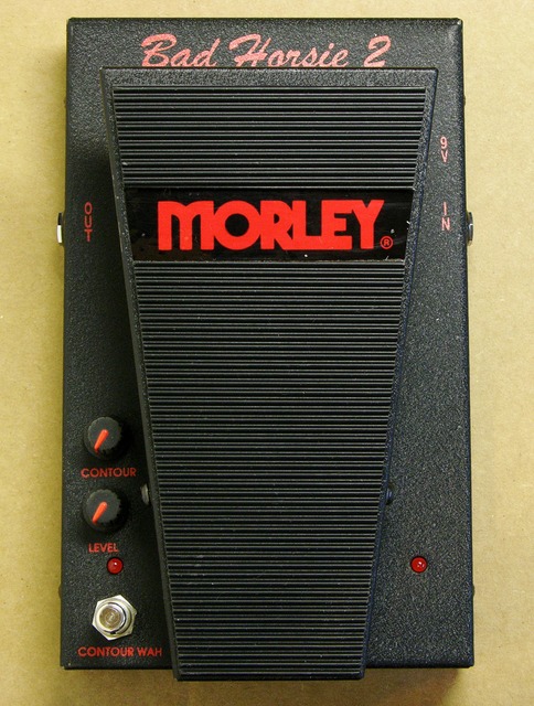
I recently ran across on Craigslist a
Bad horsie 2 that was plugged into the wrong power supply and messed up, and needs some minor electronic work.
I was intrigued by the challenge (I’m such a sucker for broken things, dang it) and bought it. When the seller and I exchanged the pedal for my cash, he remarked that he read on a forum that it probably just needed a resistor changed, and that if I were handy with a soldering gun I could probably do it myself.
Uh huh. Resistor.
Let’s dig in.
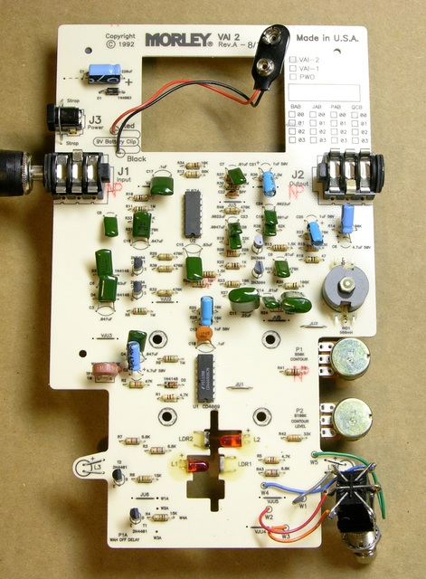
The circuit board has a hole in the top for a foam battery “cage” attached to the enclosure, something clever that I haven’t seen before. And it had no obviously damaged components.
Testing the Power Supply
Like most (all?) guitar pedals, the input jack is a switching jack — the middle leaf doesn’t contact the plug, but is a normally-open switch in the power supply circuit so the pedal is powered off until the guitar cable is plugged in.
Tracing connections on the solder side reveals an interesting tidbit — the external power supply jack is not switched; only the battery is. According to the one-page owner’s manual, the pedal only draws 16mA; so (A) it should last a long time on a 9V battery, and (B) the pedal’s current draw is probably insignificant compared to the inefficiency of the wall wart.
The power supply jack is also switched — the lower and right terminals are normally-closed, powering the pedal’s positive rail from the battery by default but disconnecting the battery when the external power supply is used.
Finally, both the battery and power jack run through a series 1N4003 diode to protect the pedal from improperly-connected power sources. If this pedal was damaged by being connected to a wrong source, it was not merely wired in reverse — that would have been blocked by the diode. It must have been connected to a higher voltage than intended.
Since I didn’t know quite what to expect from the pedal and didn’t feel like setting up an instrument and amp to test it, all of my troubleshooting was at a purely electrical level.
With a battery connected and a plug in the input jack, I measured .87V across the battery terminals, where I should have had nearly 8.4V from my NiMH 9V-form-factor battery. I also measured a fairly low resistance across the two power leads (with power disconnected). Something in the circuit had shorted and stayed shorted (instead of blowing open); and either way, it should be fairly easy to find once I knew what I was looking for.
Removing ICs
My experience with circuits damaged by power surges or other excess power is that it’s almost always the ICs — the most complex semiconductors — that blow first. So my first troubleshooting step is always to remove them from the circuit and recheck the resistance across power.
The two ICs (a TL074 low-noise quad op-amp and CD4069 hex inverter) weren’t socketed, so I needed to desolder them in order to recheck the circuit with them absent. Rather than use solder braid, I tried out my new hot air pencil that Cort bought for me (and one for himself) in exchange for building him a hotplate (that I need to assemble and deliver).
I turned the pencil up to about 350°C and waved it around the solder side of each IC while rocking an IC puller on the component side. After a little time to warm up the solder, the ICs pulled loose very cleanly.
The hot air pencil scorched the residual flux from the factory assembly,
but after wicking the remaining solder and cleaning the flux, the board looks pretty good. The vicinity of one of the two ICs shows slight damage to the epoxy (?) with the fiber substrate showing through.
Testing with ICs Removed
With the ICs out, the resistance across the power leads was very high, as I would expect it to be.
I soldered in IC sockets and measured again with the ICs reinstalled in the circuit one at a time. The CD4069 was obviously bad and the TL074 was not obviously bad. Joel had a CD4069 on hand; I installed it; and all of the pedal’s logic appeared to work — although I didn’t know yet whether the audio was working properly.
The bad 4069 does have a shiny spot on it. At first I assumed it was flux splash; but I’ve seen melt like that on ICs where the magic smoke had escaped. Maybe the spot really is a symptom of the damage.
Plugging the NiMH battery back in and powering up the pedal, I measured 3.5V across the battery leads, using either the original TL074 op-amp or a TL084 that I had on hand. This still seems like an awful lot of voltage drop for an allegedly 16mA pedal (even given the internal resistance of an aging NiMH battery); but any further diagnosis was going to require more information about symptoms.
Reassembling and Testing
Taking a chance on the TL074 (in part because I didn’t have any on hand), I reassembled the pedal with the original op-amp installed and took it to Jeremy’s house last night for him to try out. (He’s on kind of a wah pedal kick right now, and I’m feeding his habit.)
He grabbed the first power supply he saw, plugged it in, and started playing. It worked, but we had massive 60Hz hum, which didn’t really make sense — why would a fault in the pedal that I hadn’t found and fixed cause that much hum? The power supply section doesn’t have much by way of filtering, the audio section shouldn’t be specifically filtering out 60Hz, and the whole thing shouldn’t be more susceptible to hum than usual because of a broken component.
I suggested that we try a different 9VDC power supply, and went to change it out. Then I found that Jeremy had plugged my 9VAC x0xb0x power supply into my 9VDC Bad Horsie pedal. That’s right, he put 9VAC into the pedal and it still worked, albeit with hum. It was half-wave rectifying AC and that single capacitor filter was enough to get that baby going.
Which means whatever the previous owner did to it involved more than 9VAC — probably quite a bit more (or quite a bit of DC), since the CD4069 is rated for up to 15V supply. I’ll never know — although I really wish I would — exactly what he did to it. Maybe a 24V inkjet printer power supply???
After swapping in the right power supply, the pedal appeared to work correctly — although Jeremy didn’t especially like the sound running his guitar straight into the pedal. I found forum posts agreeing with his opinion that it really needs distortion before the Bad Horsie, which he played with more tonight.
While looking up the pedal’s manual today to find exactly what the controls do, I saw that Morley provides the schematic on their web site. If Jeremy decides that the audio portion of the pedal isn’t working correctly, or if I get too annoyed thinking about how much more current it’s drawing than it’s supposed to, I’ll definitely use the schematic to continue repairing the pedal. Still, this goes to show that one can do a reasonable amount of troubleshooting just by examining the construction and behavior of a circuit without having or using a schematic.


Just great.
Just missing a current measurement to have peace of mind.
You can measure the internal resistance of your nimh if you want to backtrack and get a rough idea of how much current it was using.
A new cell is around 2Ω, an older generation ~6Ω, a well used cell I have no idea.
There’s a few spare gates on that 4069, you could use one to pre-boost the signal, instead of needing a separate distortion pedal.
E.G. http://folkurban.com/Site/CMOSBoost-695.html or http://folkurban.com/Site/CMOSDrive-696.html
Another simple trick to improve the sound of many pedals is to throw a
really high-impedance FET buffer on the input (I use an MPF102 and 1M5 resistor). I see in this instance there’s already an opamp performing that function but for what it’s worth I prefer the sonic qualities of the FET. See http://www.muzique.com/lab/buffers.htm
Great description of the troubleshooting process. Thanks!