Notching a Circle in Inkscape

March 3rd, 2012 by Keith Neufeld

I needed an SVG and DXF of a circle with notches around the perimeter to laser-cut a diffuser lens and to subtract the lens’s shape from its housing in OpenSCAD. The best tool I had for the job appeared to be Inkscape (in part because I really wanted to do it with an open-source tool so it could be repeated by others), and the method was quite a process of discovery, aided greatly by John Harrison.

Here’s how I did it.

Inkscape circle with position and dimensions

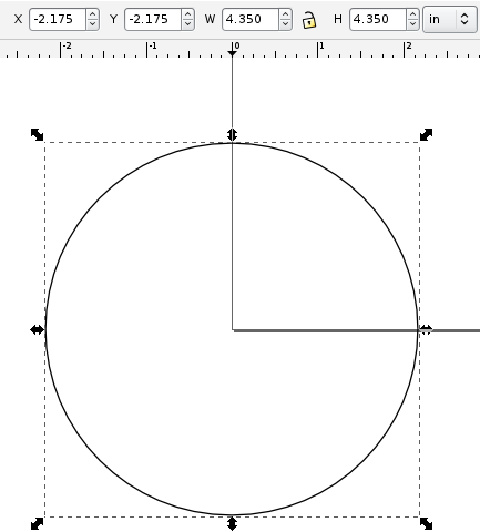
Draw the circle and use the toolbar transforms to set its diameter and position it at the origin. (Since positioning the notching figure correctly on the circle must be done in absolute coordinates, it’s easier to calculate with the circle centered at the origin.)

Inkscape circle and notching square with position and dimensions

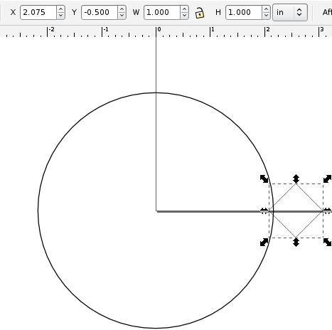
Draw a shape you want to use to notch the circle (in my case, a square rotated 45 degrees) and use the toolbar transforms to position it to notch the circle (in my case, overlapping by 0.100″, by setting the X coordinate to half the circle’s diameter minus 0.1″). The next step will be easier if you also size the shape so that its bounding box (enclosing rectangle) is an even number of the units you’re using in your coordinate system (inches).

I had hoped, by the way, to do this by insetting a circle by 0.1″ (but I can’t find how to inset by a distance other than pixels, nor to set my inset distance numerically other than zoom way in and watch the mouse position while I drag the inset control point) and then snapping the square’s position to the inset circle (but Inkscape doesn’t appear to snap to geometry).

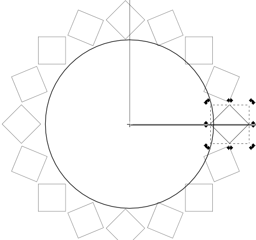
What I tried next did not work — moving the square’s pivot point to the origin and creating 16 tiled clones of the square with -100% shift X per column and -22.5° rotation per column. (I’ll show those steps later when I describe what actually did work.) For some reason, Inkscape acts as though my pivot point is 0.1045″ left of where it actually is, and I’m not willing to fuss with manually calculating the (in)correct pivot point every time I want to tile by rotation.

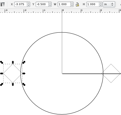
Instead, duplicate (Edit / Duplicate or copy/paste) your notching figure and move the copy to the far side, opposite your original, rotating it 180° if need be. Positioning the second notching shape is where the integer-unit-sized bounding box comes in handy — I placed mine with an X coordinate of negative (half my circle’s diameter minus the inset amount plus the notching obect’s box width), or -(4.350″ / 2 – 0.100″ + 1.000″) = -3.075″.

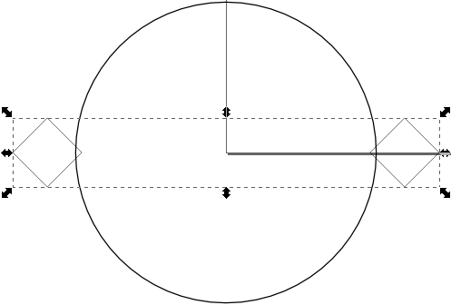
Select and group (Object / Group) the two notching figures. The next step only works on a single object, not on multiple selected objects.

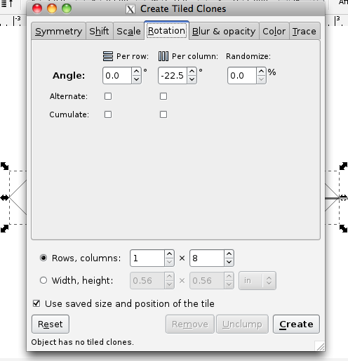
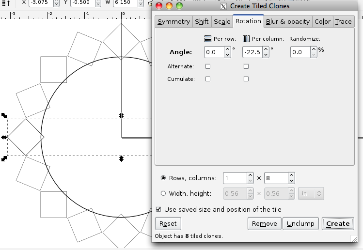
With the grouped notching objects still selected, enter the tiled clones dialog (Edit / Clone / Create Tiled Clones...). On the Symmetry tab, leave P1: simple translation selected, click the Reset button in the lower left to set everything to defaults, and change the number of columns in the Rows, columns to half the number of notches you want (since you’ve grouped two notching figures together already). On the Shift tab, set Shift X to -100% per column. On the Rotation tab, set the Angle Per column to -360° divided by the number of notches you want (-360° / 16 notches = -22.5° / notch). (Apparently Inkscape rotates clockwise for positive angles, the opposite of the entire field of mathematics.)

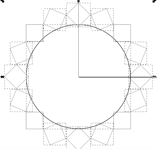
Click the Create button, note that the lower left of the dialog box tells you how many tiled clones have just been created, and slide the dialog box out of the way to view your results. If it’s not what you expected, click the tiled clones dialog’s Remove button and review and retry your tiling configuration until you get what you want. Once satisfied, close the tiled clone dialog box.

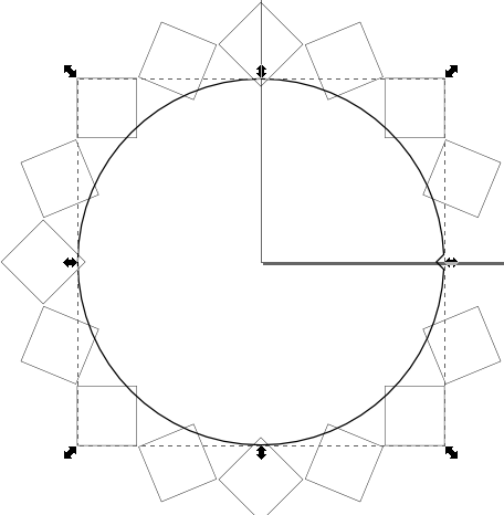
Immediately delete (Edit / Delete or press Delete) the selected figure. The tiled clone tool leaves your original figure selected and makes a copy of it at the original position; you want to delete the original before continuing.

Select everything (Edit / Select All or Ctrl A or drag a box around everything) and ungroup (Object / Ungroup) to isolate your notching figures, as the next step operates on only two shapes at a time.

Select your circle and one of the boxes and do a path difference operation (Path / Difference or Ctrl -). This should carve your notching shape out of the circle. If instead it carves the circle out of your notching shape, undo, then select the circle and lower it to the bottom (Object / Lower to Bottom) before continuing.

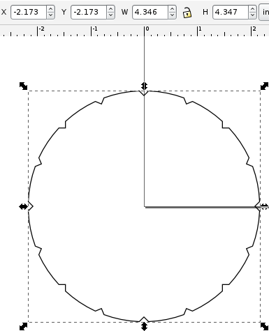
The notched circle should remain selected after each difference operation. Continue selecting additional notching figures and taking the difference until you’ve created all your notches. VoilĂ ! (Or “Viola!,” as we say on the Internet.) A notched circle.

Take care if you intend to move the circle to a specific position on your page: its dimensions may have changed, as the dimensions shown are those of the bounding box and any notches on the right, left, top, or bottom may have allowed the bounding box to creep in a bit. You may need to account for this and add a tiny offset to get the center where you want if you’re positioning the notched circle numerically.

Better Ways?

If you know an easier way to do this, I’d love to hear about it in a comment. Please try your method, right now, before posting a suggestion. It’s too easy to think something will work, or think you remember the exact details, and with the best intentions still mislead people. Always always always test your technical advice before posting it.

Why I don’t buy Duracell, Energizer, Eveready, or Rayovac

February 18th, 2012 by Keith Neufeld

LED flashlight damaged by leaking batteries

I was given this high-quality, hefty, well-balanced, well-performing LED flashlight several years ago with batteries already in it. I keep it in the glovebox; and recently when I needed it, it didn’t power on.

Packages of DieHard AA and AAA alkaline cells

In my decades of using consumer electronics, there’s only one brand of alkaline cells that has never leaked in my equipment — even things I’ve forgotten about and found again years later — and I drive miles out of my way to buy them.

DieHard alkaline cell warranty

Doubtless someone will pop up with their own horror story, but I’ll still make the claim: You will never, ever, need this.

Cleaning the Flashlight

In order to get out the crud, I disassembled the flashlight completely and cleaned it with a wire brush, a wire wheel on the Dremel, a wire brush on the Dremel, and a toothbrush and dishwashing detergent. I went a little overboard to make sure I had got it all, but at every stage I was getting out more crud.

I’ve long been impressed with the heft and solidity of the flashlight; now that I’ve seen the inside, I’m equally impressed with its design and with the ease of (dis)assembly.

Element LED flashlight, disassembled

Loosely clockwise from the left, the reflector isn’t adjustable for beam focus but screws off anyway. The heatsinked LED has a separate plastic housing with beveled forward edge that centers the LED against the back side of its reflector cone. The LED housing’s retaining ring doubles as one of the LED terminals.

The aluminum head holds the LED housing and the separate LED driver housing, dropped in from the tail end, and screws tightly to the reflector. The plastic housing for the tiny power switch and LED driver board is made of two identical, completely reversible parts, holding in the inner power switch pushbutton on the one side and leaving a window to check board orientation for assembly on the other.

The rubber outer power switch pushbutton installs after the LED driver is dropped into the head and does not seal against the housing, suggesting that the o-rings on the aluminum housing are for a great feel during assembly and battery replacement rather than for water resistance.

The battery cage holds three AAA cells and assembles easily. The stiles are marked with the cell orientation; the filled cage looks a bit like a C cell and drops into the flashlight handle, with the spring-loaded button and the metal ring contacting corresponding surfaces on the bottom of the LED board.

The tail cap doesn’t make electrical contact with the battery’s negative terminal and the flashlight body doesn’t conduct current, as it does on many less expensive flashlights (not that I think I care).

Cleaned, reassembled, and with AAA cells reinstalled, it once again works perfectly. I look forward to many more years of service … and to not having to clean it out again.

Rebuilding the CupCake Extruder Heater (When It Wasn’t Very Broken)

January 29th, 2012 by Keith Neufeld

After some success back in June using fans to cool extruded layers on my CupCake — in fact, right after that success — it slowed extruding and eventually stopped extruding altogether. This is the story of my life with the CupCake — a very brief success from time to time, but never persistent nor replicable.

When I say stopped extruding, I mean the motor actually ground to a halt. Usually it chews a divot into the filament, but this time it stopped. And I was pretty sure — don’t remember whether I actually checked the on-screen display or not — that the nozzle temperature had dropped and the filament wasn’t melting any more.

I know people talk about extruding ABS at temperatures as low as 200°C, and I don’t find that to be the case in my CupCake. Mine is calibrated, and mine doesn’t like temperatures that it thinks are lower than 220°C, and mine doesn’t really like temperatures that it thinks are below 225°C. So it really doesn’t take much to make it unhappy.

Nichrome wire crimped to teflon-coated wire

I had just rebuilt and rewound my heater at the time, and I knew that I had crimped the nichrome to the teflon-coated lead wires with silver crimp beads. I had a suspicion that the joints had become oxidized under the crimps, and the 7.3Ω resistance across my heater wires seemed high for my CupCake.

A couple of weeks ago I disassembled the heater and found that one of the two connections was indeed quite scorched and oxidized.

Nichrome wire crimped to teflon-coated wire

After cutting away the crimp tubes, cleaning the end of the nichrome wire with fine sandpaper, cutting back the lead wire, and recrimping, I tinned both lead wires with solder. Solder doesn’t stick to nichrome; but being coated with solder, the joint (which already had a solid mechanical connection from crimping) should be much less prone to oxidation.

After the rebuild, the heater measured 6.8Ω. Half an ohm difference doesn’t sound like that much until you’re trying to get to 225°C. Since power P = V2 / R, at 7.3Ω, P = (12V)2 / 7.3Ω ≈ 19.7W; and at 6.8Ω, P = (12V)2 / 6.8Ω ≈ 21.2W; so maybe that could be enough to make the difference at the high end of the extruder’s temperature range.

ReplicatorG control panel with temperature failing to reach set point

Aaaand … after reconnecting things, I still couldn’t get the temperature above 222-223°C, even though it now had some 7% more power. That doesn’t seem quite right.

Pulse-width-modulated heater signal on oscilloscope

When in doubt, scope it out. Yeah, after almost a full minute of failing to hold the temperature at the set point, the software PWM in the extruder controller was still running the heater at about a 50% duty cycle. That definitely doesn’t seem quite right.

And isn’t something I can easily fix, either. The ReplicatorG version I was running didn’t have a control panel for the heater PID settings, so (even assuming I was smart enough to fiddle them into shape) I would have had to recompile the code each time I wanted to make a tweak, which wasn’t palatable.

Firmware Upgrade

But I thought I’d heard that newer ReplicatorG versions did bring the PID coefficients into the machine control panel, so I upgraded ReplicatorG from 0024 to 0029r2, and let it upgrade my firmware from v2.4 (I think) to v3.0, and lo! lost communication between ReplicatorG and the CupCake. It said it had a connection but all the menu options to talk to the CupCake were greyed out.

Great.

This is apparently a known problem claimed to have something to do with the Mac’s localization settings for the string representation of “,” and “.” in numbers. Srsly? And the suggested tweaks didn’t fix it for me, so I’ll just wait for the next ReplicatorG release. And since the Mac package of ReplicatorG continues to be a DMG file of all the pieces you have to drag into /Applications/ReplicatorG, rather than a ReplicatorG folder that one could conveniently drag into /Applications like everyone else provides … I guess I should feel lucky to have a Mac version at all, and I’m not holding my breath for a fix on this problem.

Anyway, downgrading ReplicatorG to 0026 restored my connectivity and got me a look at those sweet, sweet PID coefficients.

ReplicatorG heater temperature graph

Which I no longer need, ’cause with the upgraded CupCake firmware, the PID algorithm seems to work right. Reaching for the knobs was obviously an attempt at a workaround, and the real fix is oh so much better.

Plastic-extruded filter holder assembly

The stringing on this diffusing filter holder is my fault, not my machine’s — I have a 0° (or 90°) overhang on a concave curve, so there’s no way it was going to come out clean. I still wanted to see what it would do, and it performed admirably under the circumstances of an impossible model.

And then stopped working again.

Filament drive motor locked up against the filament. A-gain. (Yay, great grip on the drive pulley, and nozzle retaining washer not breaking!) Temperature claims to be steady where set.

My utility is fairly cold these days. I’ll try enclosing the build chamber again in hopes that although the nozzle is hot enough, the teflon tube is too cold — but I bet I end up disassembling and drilling out the inside of the tube and nozzle again.

Should have been designed with a quick-release.

Last Stage of Circuit Board Design: Correcting for the Real World

August 21st, 2011 by Keith Neufeld

I’m working on a PC board layout for a circuit I’ve built and tested on the workbench. I enjoy board layout, but I was still delighted to be finished with the design. I printed out a copy, not to test whether all the components fit, but to stare at for a day and see whether I found anything that might need to be corrected.

Boy, did I.

Circuit board layout

In general, the first stage of laying out a PCB is placing external interface components — connectors, switches, potentiometers, etc. — followed closely by other large components and power supply traces. For me, the last stage of layout is doing a sanity check that the board will actually work (and be possible to assemble) in the real world.

Here’s what I found.

Read the rest of this entry »

Modifying a Harbor Freight Solar Charger

June 21st, 2011 by Keith Neufeld

My dashboard solar charger is one of the more useful things I’ve bought from Harbor Freight. My van has some weak short-circuit and slowly drains the battery, and as I don’t use the van all that often, I was at risk of coming out to a completely drained battery. I now keep one of these on the dash and the battery is always topped off. When I first connected it, the van was sitting in shade and the (old) automotive battery measured 5V (!); after a week it was up to 9V and after another week it was fully charged. Now I don’t ever have to think about a drained battery again. At about $20 list and $15 on sale, it’s a steal.

Harbor Freight solar charger model 44768

The bus conversion project is languishing but not forgotten, and I’ve been wanting to put one of these chargers into the bus for the same reasons as I had for the van. The wiring situation is a little different, though — the bus has no cigarette lighter / power port, I’m intending to wire 12VDC throughout the bus with Anderson power pole connectors, and I might like to have multiple solar trickle chargers (even before I install larger solar panels on the roof).

The issue with multiple panels, and even with a single panel connected to a battery that will also be charged by the alternator, and even with a single panel that may still be connected to the battery at night, is that photovoltaic cells don’t like to have reverse voltage applied. The photovoltaic effect happens in a semiconductor junction, and although I can no longer find the reference I was reading the other day, I still know the cell doesn’t do well with a reverse voltage and should really be diode-protected.

Because I wasn’t sure how much (if any) circuitry was in the panel and how much (if any) was in the automotive power plug connector, I had to take both apart to (A) make sure the panel would be diode-protected even after I chopped off the power plug and (B) see whether either held any relevant / useful circuitry.

Read the rest of this entry »

Cooling Fan(s) for Dramatic Improvement in CupCake Print Quality

June 12th, 2011 by Keith Neufeld

While trying to print a replacement cap for a spray bottle (which I ultimately want to do in PLA, but that’s what broke my extruder and I’m working my way back up to it), sizing the cap properly for the bottle was complicated by the cap shrinking unevenly while the build was still in progress. I knew I needed to turn down the build platform temperature as soon as the first layer had adhered; but the cap was so thin that the platform didn’t lose heat fast enough to make much difference.

Spray bottle caps printed on MakerBot CupCake, front side

I connected a spare DC fan to my bench power supply, set it just outside the CupCake’s build chamber, and dialed it down until it barely spun. Holy schmoly! The left cap (you’ll need to click the image for the larger version), made with no cooling, looks like an art project woven out of twigs; the next one is extremely smooth on the side that was facing the fan — better than anything I’ve printed before!

Spray bottle caps printed on MakerBot CupCake, seam side

The “seam” was on the side away from the fan and doesn’t look so as great as the fan side — but if one fan is good, two are surely better, right?

Deposition cooling fan on MakerBot CupCake

I designed and printed clips to press-fit onto a couple of 1.6″ DC fans I had sitting around (the clip is good enough to use but I have some dimensional tweaking to do before posting on Thingiverse) and positioned them at opposite corners of the build chamber, blowing around opposite sides of the object on the build platform. (Hey, I’m from Kansas. Vortices come naturally to us. Go buy a Vornado.)

The third and fourth prints above are with two fans running, trying to find optimal airspeed to cool the deposited filament but not cool the nozzle so much that the ABS solidifies before exiting. (I filed down the seam on the fourth; it didn’t really print quite that well.) I think the ultimate combination may be an enclosed build chamber to raise the overall temperature and fans to cool the layer just printed.

Many CupCake, RepRap, and Hydraraptor operators have added cooling fans, but I don’t recall seeing dramatic before-and-after pictures. Based on what I’ve observed during mesmerizing hours of watching the CupCake print, it’s obvious why it helps — without active cooling, the previous layer is still molten enough that the soft extrusion being deposited by the nozzle still applies enough force to squish the previous layer out of the way in some random direction. It may have been deposited in the right place, but it’s not in the right place any more after the next layer moves it. With cooling, it stays put.

Z-Axis Wobble and Ooze

The CupCake carries the extruder up and down on a platform supported by four threaded rods. It’s a very economical design, but the rods are less precisely straight than Acme threaded rod and aren’t a perfect fit for the ID of the pulleys at the top. The combination of these factors results in the extruder platform swaying from side to side as it moves up and down. The effect is very visible during high-speed movement but still present during low-speed movement.

Spray bottle caps printed on MakerBot CupCake, closeup showing Z-axis wobble

My printed objects are finally at a high-enough quality that I can see the Z-axis wobble represented in the perimeter of the object. The faint ripples visible toward the left edge — about four and a half filaments high — match the thread pitch of the threaded Z-axis rods and are caused by the extruder circling through the X-Y plane as it raises during the print.

This effect is well-known and is a solved problem. Thingiverse user “twotimes” has designed a wobble arrestor that adds rigid, smooth rods to the Z axis and new bushings attached to the extruder stage to follow them in a perfect vertical motion. It’s time!

Cooling fan printed on MakerBot Cupcake, front-side closeup showing Z-axis wobble

The ripple is visible at the left end of the elevation view of this fan clip (and more obvious in person than in the photograph), but it is other imperfections that catch my eye. From the front, the bottom section looks very good, but the tower at the top (which once installed is the lower part of the extruder stage clip) has considerably more variation in filament position.

Cooling fan printed on MakerBot Cupcake, back-side closeup showing blobbing after non-contiguous perimeter

From the back, note the relatively high quality up to the top of the rearward extension for the clip — until which point the entire object has a single, contiguous perimeter. Above that level, the quality of the rear tower is much worse and the wall facing it is somewhat worse than below. The quality of the forward tower drops precipitously after the top of the main clip body.

Some of this may be due to the smaller cross-section leaving less time for the fan to cool the filament, but I place most of the responsibility on the filament drive in my extruder. It’s still the DC gearmotor design; the geartrain has a lot of backlash; and it’s not good at fast reversals. I’m optimistic that a stepper design will control the oozing, already improving the print quality, as well as making it practical to enable Skeinforge’s Cool plugin to pause printing between layers while the fan cools the just-extruded filament.

Another CupCake Nozzle Jam, PTFE Thermal Barrier Swarf, Heater Winding, and Glass Transition

June 12th, 2011 by Keith Neufeld

I had written about jamming my CupCake nozzle trying to extrude PLA and having to disassemble the whole nozzle to clean and rebuild it. I got new PTFE thermal barriers (the white Teflon® tube) from MakerBot, put things back together, and quickly jammed the heater with ABS, which I’d never done before.

MakerBot CupCake Plastruder MK3 heater barrel with ABS leaked around barrel/barrier junction

I conversed with Nop Head about the increased force required to push filament through the heater and he pointed me to the junction between the brass heater barrel and PTFE thermal barrier. It needs to be absolutely closed, and when reassembling I’d left a tiny gap into which the ABS expanded (covering the end of the brass in the photo), interfering with smooth flow of more ABS into the brass. He gave me this video link to a vivid demonstration of the phenomenon, in which he is attempting to push filament into a heater assembly that’s wide open at both ends:

He gave me the tip to reassemble the brass heater and PTFE barrier with a drill bit of the nominal hole diameter inserted. When the two are turned together as tightly as they should be, the PTFE will begin to deform and just barely begin to grip the drill bit.

Believing the filament hole through the PTFE is metric and not owning metric drill bits, I figured the next best thing would be to use filament itself (which would be slightly undersized; but I could tighten until friction increased and then back off slightly). To my surprise, I couldn’t push filament through just the PTFE tube by itself.

Upon inspection, I discovered swarf where the little filament hole from the top meets the larger heater hole from the bottom, and this swarf was interfering so much with the motion of the filament that even after forcing the filament end past it, I still had difficulty moving the ABS filament through the tube. No wonder the heater was jamming!

I reached into the large end of the hole with a rat-tail file and used its tip to push the swarf into the small hole, then filed it free by push-filing upwards into the hole. After cleaning the PTFE thoroughly, I reassembled the heater and fired it up again.

In the past, I’ve been able to hear my stock DC gearmotor slog down when the filament reaches a certain point inside the heater, and I’ve always assumed that was due to the constriction of the nozzle. Not so, as my motor no longer slogs, and instead merrily pushes filament through like chocolate sauce dribbling out of the corner of a topping pouch! I have to assume that my original PTFE barrier had the same problem (to a lesser extent) all along, and I wonder how many others out there do too.

Thermal Gradient and Glass Transition Phase

While rebuilding the heater, I initially thought that part of my original problem must have been the top of the brass getting hot enough to melt the plastic filament that close to the PTFE, as I had always pictured the filament melting somewhere inside the brass. I’ve also read about hot-end designs with a heater near the tip and a heatsink higher up to keep the feed area cool and the plastic solid while inside it.

MakerBot CupCake Plastruder MK3 heater with nichrome wound near tip (doesn't work well)

I thus rewound all of the nichrome near the nozzle end and thermally insulated only the tip, thinking the cooler area above would help keep the filament from melting within the PTFE.

MakerBot CupCake Plastruder MK3 heater insulated only at tip

Even though after deswarfing the PTFE, the extruder initially worked far better than it had before, it proved not to be as reliable as desired, and I did notice the filament feed beginning to bog down. I had an ongoing email conversation with Nop Head, and he gave me this fantastic explanation of the hot end, which I reprint here with his blessing:

Most of the temperature is dropped across the PTFE and the point where the plastic melts (when stationary) will be about half way between the end of the barrel and the top of the insulator. This is where it is most viscous, so it is is good that it is inside something very slippery.

Brass is about 1000 times more thermally conductive that PTFE, but the barrel has a much smaller cross sectional area, so the thermal resistances are not as far apart as that, but still considerably different.

When the filament is moving the melt point will be much closer to the top of the brass due to the time it takes to melt because ABS is also a very poor conductor of heat and has a high specific heat capacity.

It’s a shame PTFE is not transparent, as it would be a lot more obvious when things were not working.

I think when at rest the filament melts in the PTFE. When moving I think it only gets above the glass transition, so when there is a gap it expands into it and jams.

Well, heck! If that’s the way it works, it sounds like I want the brass heated evenly (at least in this Plastruder MK3 design) to keep the filament as soft as possible at the brass-PTFE junction.

MakerBot CupCake Plastruder MK3 heater barrel with nichrome wound around entire length

I disassembled the heater yet again, this time rewinding the nichrome as evenly along the length of the barrel as possible and once again insulating the whole barrel. After reassembling, I haven’t noticed the feed motor bogging down as it was before.

Stratasys ABS Rapid-Prototyping Machine

May 30th, 2011 by Keith Neufeld

Another heretofore unfinished old post, this one from January 2010:

I was over at the aviation department last week and happened upon the installation of a new Stratasys rapid-prototyping machine.

Stratasys ABS rapid-prototyping machine, front left view

It has a much larger build chamber than NIAR’s previous ABS machine — this one is something like 14″ x 14″ x 18″.

Stratasys ABS rapid-prototyping machine, left side open

The case was open and I was intrigued by the thick blanket of insulation around the build chamber. I asked the installer if the whole chamber was heated and he said yes, to 80°C. Interesting point of reference, as RepRap / CupCake owners seem to have settled on 60°C as the standard temperature for heated build platforms.

Stratasys ABS rapid-prototyping machine, hazy shot of extrusion head

It was fairly dark inside the build chamber and I couldn’t get a great shot with my cell phone camera, but you can see the extrusion head with two nozzles for support and build material. I found it interesting how extremely broad and shallow the white nozzle cones are — maybe it helps prevent snags?

Filament from Stratasys rapid-prototyping machine

With the lab manager’s blessing, I fished two filament strands out of the trash. The upper, black filament is ABS; the lower, translucent brown filament is a dissolvable support material that apparently washes out in an agitated hot water and detergent bath. Wish I knew exactly what it was!

I measure the diameter at .070″ ± .001″ ≈ 1.778mm ≈ 1.75mm ≈ .069″, so it looks like they’re using 1.75mm filament. The stretched section on the end is recognizable as having been in the hot end and then backed out.

Note the toothmarks all the length of each filament (about 3m), suggesting that either something is pushing the filament from that far back or (more likely) the hot end has a quick-release for cleaning and this filament was run through the machine after removing the hot end.

PLA + Ignorance = Broken Extruder

May 29th, 2011 by Keith Neufeld

I got a roll of PLA to try making some clear objects on the CupCake. I had read on the MakerBot wiki about the techniques for and challenges of printing PLA but still had trouble feeding PLA into the Plastruder MK3 and chasing out the ABS that I’d been using.

MakerBot CupCake Plastruder MK4 with stripped PTFE barrier

When feeding in the PLA, ABS came out for a while and then things stopped. Something happened inside the PTFE (Teflon) thermal barrier and the brass heater barrel was pushed out the bottom.

Later kits have a nut between the PTFE barrier and the metal washer so the long black bolts pulling on the washer in turn pull on the nut which has a stronger grip on the threads than the PTFE, dramatically reducing the risk of the brass barrel slipping out of the PTFE barrier and dramatically increasing the risk of cracking the acrylic retainer at the top. It’s recommended to replace it with a metal retainer.

PLA clogged on MakerBot CupCake Plastruder MK3 nozzle assembly

Today I had time to disassemble the Plastruder and unthread the heater barrel from the PTFE barrier. Looks like the PLA melted, the PTFE got warm and softened, the PLA oozed around the heater barrel, and then the PLA solidified and the barrel was pushed out the end of the softened PTFE.

I chipped the hardened PLA off the end, then searched for a solvent that would dissolve the PLA out of the barrel. I was surprised to find no information online (I do not assert that there isn’t any but merely that I didn’t find it) and tried acetone. During the time I waited, it didn’t dissolve the PLA completely, but it did soften it enough to scrape it out of the threads with a wire brush and goop it out of the barrel with a drill bit.

Scorched nichrome heater wire on MakerBot CupCake Plastruder MK3 nozzle

Since something in the thermal insulation had been previously damaged by deliberate immersion in water, I ended up deciding to peel apart the whole heater assembly. I suspect the water-soaked kapton tape adhesive closest to the nichrome heater is what scorched and I still have faith in the magical powers of kapton. I just know its weakness now.

On the bright side, I get to rebuild my heater from scratch and make it beautiful again.

On the dim side, I need to replace the PTFE barrier, which is swollen beyond even making contact with the brass threads, and the ceramic insulation that wrapped the heater, which was no longer pristine. I see that the MakerBot store has them in stock and affordable, and I reckon I’ll order them this week unless I hear a brilliant alternative first. The nichrome wire’s fiberglass insulation looks and feels intact — I think it’s saturated with scorch from the kapton rather than being damaged itself — but I’ll probably order more of it too.

Anyone successfully using PLA, I’d love to hear what temperature works well for you and what technique you use for changing from ABS to PLA.

Solar Charging and Switching Circuit for Outdoor Sculpture Installation

May 29th, 2011 by Keith Neufeld

Over the winter, my friend Steve Atwood got a commission for a sculpture to be installed in the Wichita Falls, TX Kemp Center for the Arts “Art on the Green” sculpture garden from May 2011 – 2012.

Lure 22 V2.0 by Stephen Atwood at Kemp Center for the Arts, Wichita Falls, TX

He had in mind to continue a series of his sculptures based on the form of a fishing lure but wanted to enhance this sculpture with one or more LEDs, preferably that would come on only at night. We discussed a wide variety of options that we hope to develop for another installation in the future; but in the end, in the interest of time for this project, Steve found control modules that flash up to five LEDs at random and installed them behind a set of cones protruding from a recessed panel.

He asked how to make the LEDs turn on at night and also wondered whether he could power them for a year from a primary battery or whether he should use rechargeables.

Lure 22 V2.0 by Stephen Atwood at Kemp Center for the Arts, Wichita Falls, TX

About seven years ago, I had come into possession of some discarded solar yard lights, and out of curiosity had reverse-engineered their charging and control circuits. Since yard lights accomplish both functions — charging and switching — I figured the circuit would be perfect for the sculpture. I was able to find one and instruct Steve how to modify it for his needs.

Solar yard light schematic

The circuit is very simple and I find it rather elegant. During the day, the solar panel assembly (left — for want of a proper schematic symbol, I just drew another battery) charges two AA cells through a diode that prevents the battery from damaging the panel with reverse voltage at night. Additionally, through the R1 – R2 voltage divider, the solar panel pulls up the base of Q1, switching it off and allowing R3 to pull up the base of Q2, switching it off and switching off the load LED1.

At night, the panel’s output approaches 0V and R2 pulls down Q1‘s base, causing Q1 to conduct and pull down Q2‘s base (in a Darlington-like arrangement — I don’t know whether it’s still considered a proper Darlington with R3 pulling up the Q1 emitter – Q2 base connection), switching on Q2 and LED1. In fact, depending on the panel’s exact voltage, the load may switch on even before full darkness, and R1 – R2 can be tweaked to tune the turn-on point.

Control board from solar yard light, modified

Steve removed the LED from the control board and replaced it and the fly wires for the solar panel and battery with screw-terminal connectors for ease of installation inside the sculpture. He bought a new solar panel with a higher output voltage to charge the higher-voltage battery for the white LEDs he wanted to use (the yellow LEDs in my yard lights didn’t require as high a forward voltage) and milled a Lexan cover for it to protect the panel from hail, with an O-ring groove to protect it from rain as well.

With higher battery and solar panel voltages, Steve indicated the load was turning on before the ambient light got as dark as he wanted, so I told him how to locate R1 and replace it with fly wires to a 100K pot. After the swap, he said he was able to tune it perfectly and he was delighted.

Lure 22 V2.0 by Stephen Atwood at Kemp Center for the Arts, Wichita Falls, TX, night view

I’ve not had a chance to visit the sculpture garden and probably won’t while Lure 22 is installed. If anyone’s in the area, I’d love to hear from you how well it’s working and how well the electronics hold up over the course of a year outdoors.