Archive for June, 2010

Installing Batteries in a Liebert GXT2-2000RT120 UPS

Sunday, June 27th, 2010

A while back, I bought a secondhand Liebert GXT2-2000RT120 uninterruptible power supply (UPS) on eBay. The GXT2 is a series of online UPSes, meaning that the output power always comes from the inverters off the battery bank; it doesn’t switch from utility power to battery power like an offline UPS. Besides eliminating any possible switchover glitches, online UPSes always deliver conditioned power at a constant voltage. The 2000RT120 is a 2000VA unit with 120V output — large enough to power all my servers for a good little while.

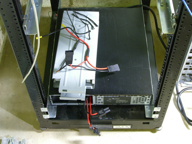
Liebert GXT2-2000RT120 UPS with battery cage disassembled

The batteries were due for replacement and the seller removed them to save on shipping costs. I got a UPS with a set of wires and no instructions on how to connect them.

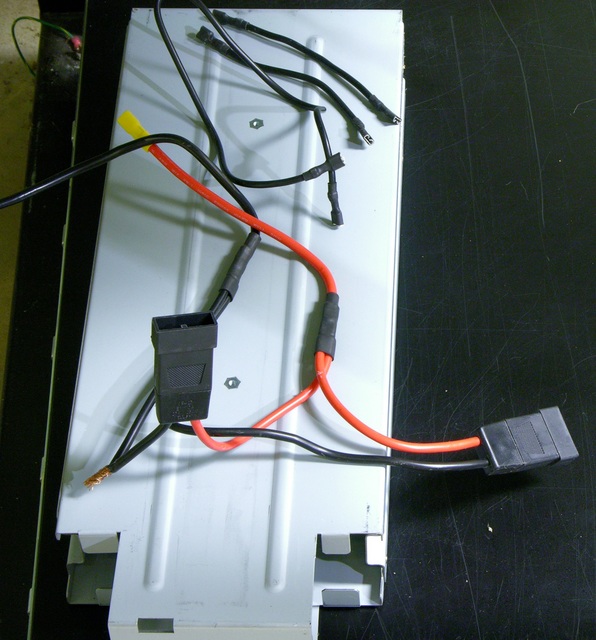
Liebert GXT2-2000RT120 UPS battery wiring

Also one of the wires was compromised … but since it appears to be a ground wire, I figured no big deal if it shorts out against the cage. KIDDING!

Yesterday I figured out the wiring, installed batteries, and got the UPS set up in my server rack.

(more…)

Q&A: PIC Programmer, Oscilloscope

Saturday, June 19th, 2010

I get very specific questions via my contact form, but also questions about more general issues that might be of interest to a larger audience. I’m going to start posting the latter category here.

PIC Programmer

Trey asks:

Do you have any recommendations regarding a Microchip programmer? There is the PicKit 2 and the Pickit 3. I have read that there are/were issues with the PicKit 3. I know you have used Microchip parts in your designs, but was wondering what your opinion was?

Trey, I’ve never used a PIC that wasn’t already preprogrammed with the LogoChip environment, so I have no experience with PIC programmers.

After reading through PIC and Atmel datasheets in considerable detail to access hardware features on both platforms, my opinion is that I’ll never use a PIC. That’s based on a couple dozen small things that I don’t even remember any more, but which added up to a pretty powerful opinion that Atmel builds a much better thought-out microcontroller that’s much easier to use.

But … that’s not the answer you were looking for. Readers with PIC experience, can you address Trey’s question? Please clearly phrase your responses as statements of opinion (like my opinion above, which is nothing more than an opinion) or as statements of fact with links to supporting information.

Oscilloscope

I am just now starting my journey into electronics and was wondering if you have any recommendations for any particular make/model of oscilloscope?

For someone starting in electronics, before an oscilloscope, I would recommend:

  • A $3 multimeter. I’ve started buying a few of these whenever I go to Harbor Freight and find them on sale, and I give them away like candy. Ace Hardware also sometimes has cheap meters in the dump bin.

    Is this as accurate as a Fluke? Of course not — but for basic electronics troubleshooting, this is more than adequate. The one useful function it lacks is a beeper for continuity testing — you do have to look up at the screen to read low resistance.
  • A breadboard and some components with a list of projects to try. I’d suggest Adafruit’s $50 Arduino budget pack, $65 Arduino starter pack, or $85 Arduino experimentation kit. Even if you’re not that interested in embedded design, the Arduino is a great platform for trying things out and interfacing to the analog electronics, and the Adafruit kits provide a list of experiments to use as a starting point and get the ideas flowing.

But if you’re already doing PIC programming, you seem to be well past the resistors-and-LEDs stage. If you really need a way to visualize signals in order to progress, my oscilloscope recommendation would be whatever working scope you can get for the lowest price, making sure that you do end up with at least one probe (or find a cheap one on eBay).

I paid $25 for an old, used scope about 20 years ago and have only upgraded to a better scope in the last couple of years — which is 20 years old, which I got from a friend of a friend, and which I haven’t put on my bench and started using yet.

The two times I’ve used a different scope are when I found a cheap scope with X-Y inputs that I use for troubleshooting vector arcade game displays, and when I borrowed a digital Tek scope for doing some precise high-frequency measurements.

Granted, I don’t use my scope for calibrating circuits. If you need to do that, you need a better scope, and one that’s calibrated, and that’s going to cost real money. But if visualization is what you’re after, then the cheapest scope that works will do the job.
Lacing the x0xb0x Wiring Harnesses

Sunday, June 6th, 2010

This isn’t part of a normal x0xb0x build so I didn’t throw it into my build notes, but I had fun figuring out how to route and lace the x0xb0x’s wiring harnesses. I know lacing is overkill for this; but without some kind of cable management, the individual wires of each cable wouldn’t even stay together. Had the kit included ribbon cables, I wouldn’t have bothered.

Planning the Paths

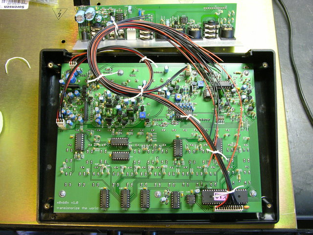
First pass at x0xb0x cable routing

Besides the obvious goal of keeping the wires tidy, my main goal was to position slack in the cables so that the back panel could be lifted out of the case and set to the rear, allowing full access to both circuit boards, without disconnecting anything.

Before doing any real lacing, I mocked up the cable path to make sure everything would work. My first attempt, here, had enough length for the J3 bundle from the lower right of the main board to the right end of the I/O board; but J7′s wires coming from the left edge of the main board looped around too much before heading to the I/O board and didn’t reach their destination.

(more…)

Building the x0xb0x

Sunday, June 6th, 2010

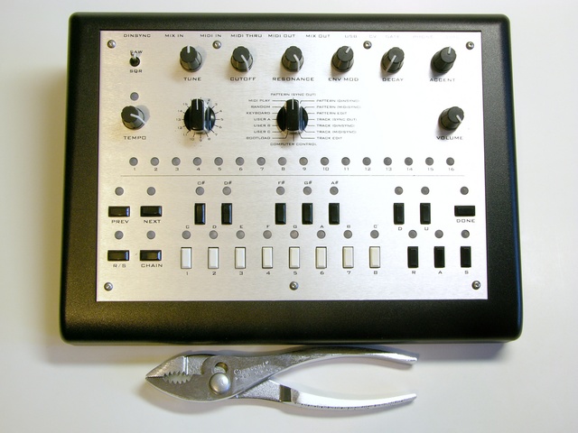
As I noted previously, I recently got a x0xb0x kit. The x0xb0x is an open-source-hardware replica of the 1980s Roland TB-303 bassline synthesizer (and sequencer) that was influential in the development of acid house music. Limor of Adafruit Industries and a mysterious, anonymous German studied the TB-303 schematics and measured the behavior of its now-rare semiconductors and designed a replica with the same analog circuitry and new digital features, including MIDI I/O (supplementing Roland’s pre-MIDI “DIN sync”) and simpler sequencer programming.

Assembled x0xb0x, top view

Adafruit produced x0xb0x kits in batches of 100 as Limor was able to track down enough “rare parts,” order circuit boards, and assemble the common parts into kits. I’d been on her waiting list since 2008, so was terribly disappointed when she officially announced what we had all come to realize anyway — that tracking down the rare parts was becoming enough of a hassle, she wasn’t having any fun doing it and wasn’t going to produce any more kits.

Happily, Limor announced shortly thereafter that thanks to Adafruit’s open-source hardware license, James Wilsey of Willzyx Music in Taiwan has taken up the torch and would shortly be offering x0xb0x kits.

(more…)