Archive for March, 2009

DIY Power Injector for Axis 2100 Network Camera, Part I: Investigation

Tuesday, March 24th, 2009

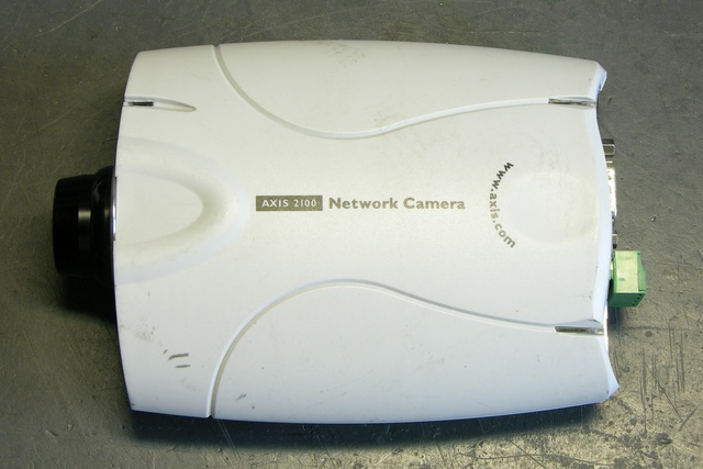
A little while back I bought a couple of used Axis 2100 network cameras, intending to use them at home (driveway cam? front yard cam?) to replace my lousy Linksys WVC54GC. The Linksys’s video stream is viewable only in Internet Explorer or with VLC; the Axis (although older) streams motion JPEGs that can be viewed with just about anything, provides still JPEGs, and has FTP server upload capabilities to update a statically-served image on a web server.

Axis 2100 network camera

Power Over Ethernet and Power Splitters

Having got them, I decided I’d like to play with one at work, installing it in our 3rd-floor bay window overlooking campus, so those of us with windowless offices can get a little sunshine in our lives. That would be easiest if we didn’t have to run both ethernet and power to the camera separately, so I started reading up on the camera’s power capabilities.

Power over Ethernet (PoE) is a standard for delivering 48VDC over an ethernet cable — depending on the implementation, possibly on the same pairs used for data, possibly on the spare pairs. The data pairs use differential signaling (the difference between TX+ and TX- is the signal, like balanced audio, as opposed to a single signal referenced to ground), so the DC power can be provided on the two wires of one pair and grounded on the two wires of the other pair (similar to the way phantom power is provided on balanced audio cable).

The product web page almost intimates that the camera supports PoE:

  • Access to a power outlet not needed with use of Power over LAN Midspan and Active Splitter from Axis
  • No need for power outlets and electrical cabling using Power over Ethernet products

But in fact the camera doesn’t operate when hooked to a PoE connection. Additionally, another Axis page lists a “PoE splitter” for the camera, which strongly suggests that power may be delivered over the ethernet cable by standards-based or non-standards-based means, but must be split externally before entering the camera.

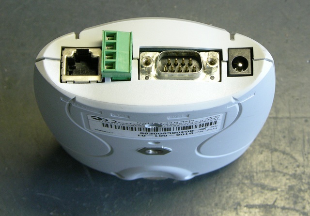
Axis 2100 network camera, end view

Still, pp 59 and 62 of the users guide show intriguing connections among the I/O port, the power connector, a bridge rectifier, and a switching power supply; and p 65 lists the power supply as accepting 9-15VAC or 9-15VDC, which is kind of interesting. Even though the unit clearly doesn’t function on PoE, I thought it was worth opening up to see whether it would accept non-standards-based power on the ethernet port.

By the way, recognize that green thing?

Going In

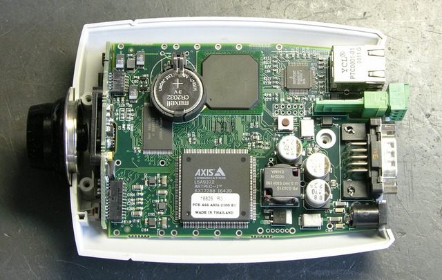
Axis 2100 network camera main PCB

Here’s the camera with the bottom of the case lifted off. Note that the top of the circuit board faces the bottom of the enclosure.

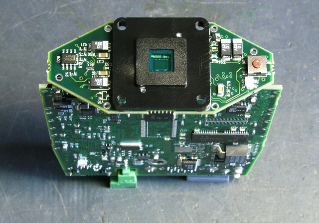
Axis 2100 network camera CCD

The CCD is on a separate PCB stuck onto the end of the main board.

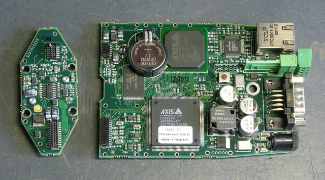
Axis 2100 network camera PCBs

Another view of the top side of the board with the CCD board separated.

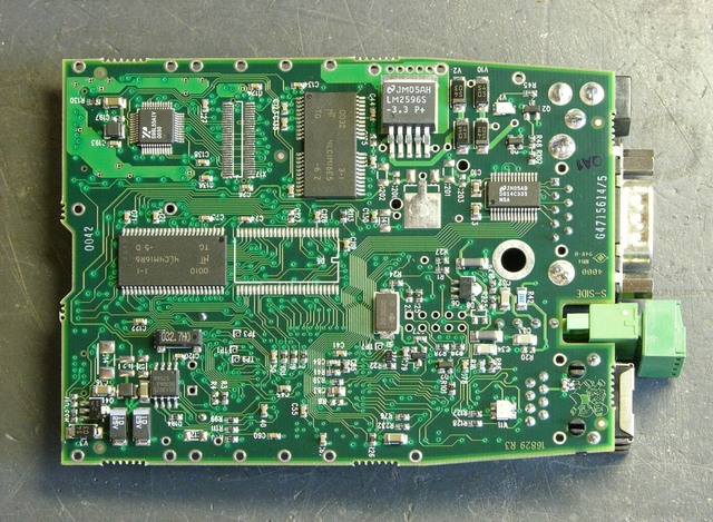
Axis 2100 network camera main PCB, back side

And the bottom of the board (facing the top of the enclosure).

Continuity

I started by trying to trace connectivity from the power jack to the unit’s ground, not remembering that the camera accepts AC input. I got no continuity there, as my tester doesn’t indicate continuity through diodes. After noticing the bridge rectifier (last photo above, just to the left of the upper right corner), I realized my error and was able to trace ground from the rectifier output throughout the unit.

Next I traced from the power jack to the I/O connector and confirmed the connections shown in the user guide — you can provide or draw rectified and filtered but unregulated DC power on the I/O connector.

Feeling bold from my discoveries, I checked continuity to the ethernet jack. I got DC continuity between ground and the center pins 4-5, but no other connectivity. Bah! No non-standards power on ethernet for me.

Hm, but I also hadn’t successfully traced V+ from the rectifier throughout the unit. I figured I needed to pick it up from the other side of the LM2596 voltage regulator — which turned out to be a switching step-down regulator.

LM2596

Pin 4 is the feedback that connects to the filtered, regulated output — and indeed, it connects to the V+ power supply pins of all kinds of things throughout the circuit. Cool; progress! Maybe the regulated DC voltage connects to the ethernet jack???

Mm hm, it sure does. I get DC continuity with .4-.5Ω resistance from the V+ rail to ethernet pins 1 and 2 (TX+ and TX-), DC continuity with .2Ω resistance to pin 3 (RX+), and no connection to any other pin.

So?

Although the datasheet’s application circuit above shows the 5V step-down regulator, the camera actually uses the LM2596S-3.3 for 3.3V power. That this appears on both TX pins of the ethernet port suggests that I could provide DC power on pins 1-2 and ground on 4-5.

But it would have to be regulated 3.3VDC, which (1) isn’t standards-based PoE and (2) isn’t going to travel well over 100+’ of cable. This suggests that a non-standards-based switch-end power injector directly in through the camera’s ethernet isn’t going to work well.

More plausible: Build a PoE-attached power supply with a 48V-3.3V step-down converter and hang it off the back of the camera. At first I thought that doing PoE would require a dedicated PoE chip to do the negotiation, but all that’s needed is a 25kΩ resistor across the powered pairs. So it really would be feasible to do, without a special chip just for the PoE.

However, if the solution is going to require external PoE down-conversion anyway, why bother going all the way down to the regulated 3.3V? Why not go 48V-12V and come in the regular power jack, which also eliminates any risk of making the LM2596 unhappy by feeding power into its output? (Its block diagram looks like that shouldn’t be a problem, but I don’t know enough to be certain.)

If using an external down-converter anyway, the only drawback I can see of splitting the power out to feed the the power jack separately rather than the ethernet is the requirement for an extra connector.

Or the Simple Way

Regardless, I don’t really want to have to build an external step-down regulator just to get the cameras working. So for now, I’m more likely to build simple cable splitters to inject 12V onto unused pairs at the switch end and split it out to the power jack at the camera end.
ABS Puck Case Prototype

Saturday, March 14th, 2009

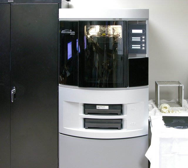
Dimension Elite 3D Printer

A while back, I had contacted Brian Brown, associate director of the CAD/CAM lab at the university’s National Institute for Aviation Research and a great colleague of mine, to ask whether they had any rapid-prototyping machines that could churn out a prototype LED puck case in a transparent or translucent material.

Dimension Elite 3D printer

They didn’t at the time, but Brian contacted me last week to say that they had a new Dimension Elite 3D printer and they’d be happy to print me a case while they were ramping up on learning to use it. I emailed over an STL export of my Blender model, Brian put his student Jonas Fink to work, and the next day I went over to take pictures of the machine in operation.

As it turns out, the “natural” colored ABS plastic isn’t translucent enough to use as a functional test enclosure, but it makes a great physical prototype. More on that in a bit.

How It Builds

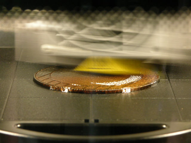
Dimension Elite 3D printer building support structure

The machine extrudes a tiny “string” of ABS plastic onto a removable tray. It first lays down a brown support structure to hold up any overhanging areas, and the support material is a soluble form of ABS that’s later removed in a detergent bath. The extrusion head moves around one entire horizontal plane, “drawing” in all the material that appears there, then lowers the tray slightly and draws in the next layer.

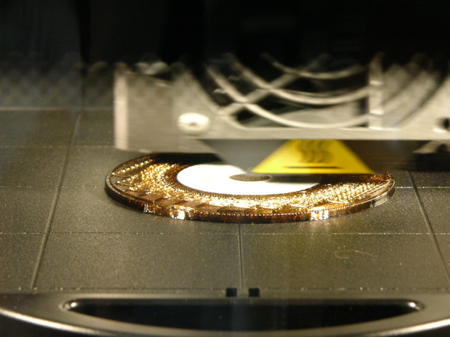
Dimension Elite 3D printer beginning to build puck case

Once the support structure is in place, the machine extrudes plastic for the actual model — still continuing to build support structure for higher overhangs. My puck case was being built upside-down (as a bowl instead of a dome); so here you can see the puck material in the center as the machine works its way out from the low center of the bowl up the curved edges.

Breaking It Loose

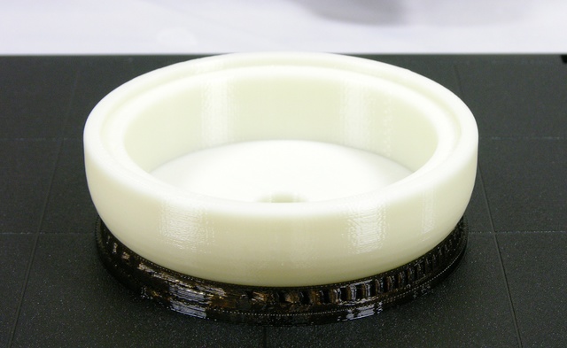
Completed ABS puck case prototype, front view

The build ran past the end of the work day, so I went back the next morning to see the completed prototype, still attached to the tray. If you look closely, you can see the layers of “threads” that were used to built up the model, with the support structure underneath.

Completed ABS puck case prototype, support structure upper front

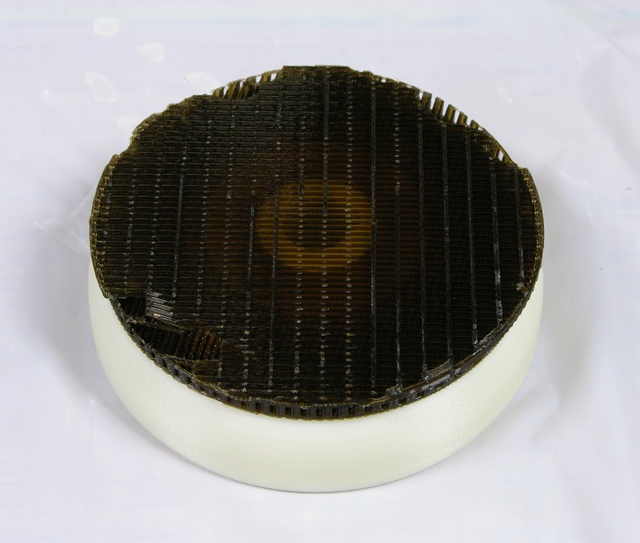
After breaking the model free of the tray, the sparse honeycomb-like nature of the support structure is even more evident. The light ring in the middle is the bottom-most layer of model plastic surrounding the hole for the pushbutton switch.

Although the suggested means of removing the support structure were to put the whole piece into the cleaning tank for a few hours and let it dissolve, I was curious how sturdy the support was and found that I could actually pry and crack it loose of my model using my pocketknife. I managed to get the whole thing cleaned off without using the tank or cutting off a finger.

The Result

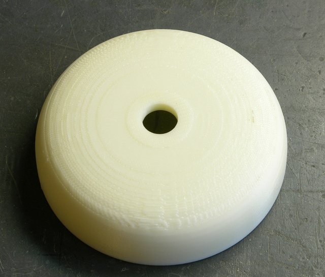
ABS puck case prototype

The finished prototype is rougher on the top than I expected — this machine (at least as programmed for this run) doesn’t seem to build a smooth finishing surface on the support structure before beginning to build the model, so the first surface of the model has the jaggies. You can easily see the contour become smoother around the knee of the curve, where it stopped building support because the slope of the overhang could be built directly.

I’m guessing if the machine did lay down a smooth layer of support before starting the actual model, I wouldn’t have been able to break off the support as easily, and I would have had to use the cleaning tank. That still seems like a good tradeoff for a smoother model.

As to the utility of having an opaque prototype of a clear case — pretty darn high. One of my puck design goals is that its size and shape make it comfortable to carry with me all the time, preferably in a back pocket. I’ve been doing exactly that since Tuesday with this ABS case, and I gotta tell you, it’ll work great. No complaints yet, sitting on it all day, driving, you name it.

Fitting Batteries

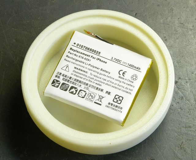
ABS puck case prototype with iPhone Li-Po battery

A little over a year ago, I had been really pleased with the service I got from eBay seller Digital Power Pro on a replacement battery for my Visor Prism, and contacted them to ask whether they sold any Li-Ion or Li-Po batteries with the mAh rating I was looking for and of a size that would fit inside my puck case. They were entertained by the question, and recommended an iPhone replacement battery and an HP Jornada battery.

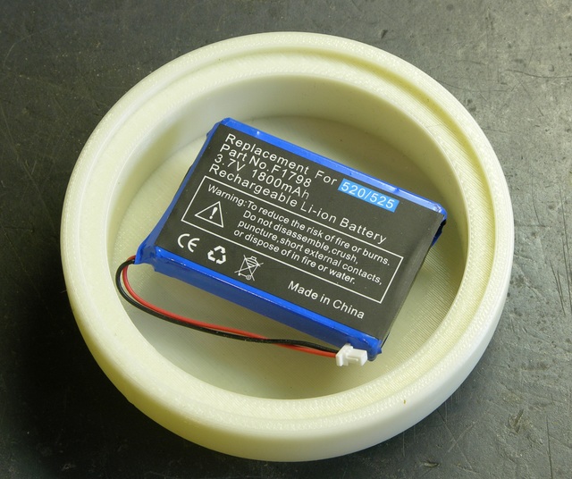
ABS puck case prototype with HP Jornado Li-ion battery

They both fit nicely into the recess, with the iPhone battery being a little slimmer in case I run out of room.

Next step: milled acrylic case.

Fixing My Wife’s Curling Iron

Saturday, March 14th, 2009

When my wife leaves her curling iron on top of a note that says “Non-connected wire somewhere? goes in & out of power,” my first thought is, who taught you English?; and my second thought is, I better stop making fun of her long enough to get this fixed before she gets home from work.

My belated third thought is, I finally get to see how the infinitely-spinning power cord connection works . . . and I bet it’s the problem.

It’s tough always being right.

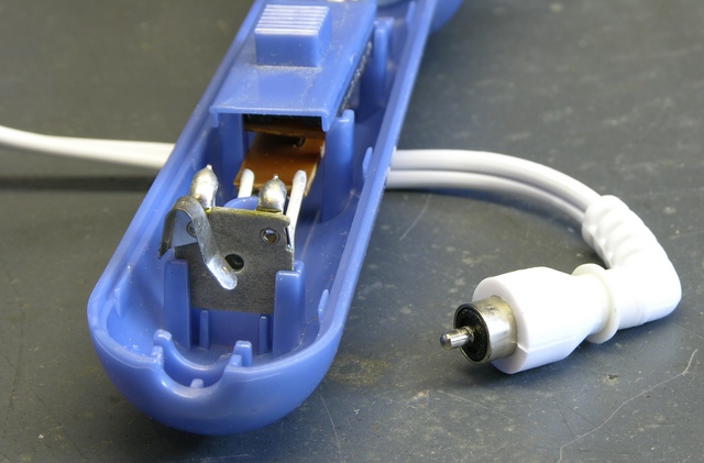
Curling iron power cord connection

The power cord has a connector that looks a little like an RCA plug, except the barrel portion’s outer surface contacts the jack’s leaf instead of the inner surface contacting a barrel jack.

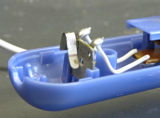
Curling iron power cord connection, closeup

You can see the pitting on the leaf where the contacts had arced, probably at least in part due to oxidation of the surfaces. Also, the leaf was twisted so it was making contact only with the leading edge of the barrel instead of with the whole face, which exacerbated the problem by reducing the contact area to a very small point that became completely pitted.

After smoothing the pitted area and polishing the tip and ring leaves and the tip and barrel with 600-grit sandpaper, I reinstalled the power cord and carefully twisted the barrel leaf parallel to the barrel so they mate over a larger surface area.

Once the whole iron was reassembled, I plugged it in and watched its power lamp while spinning the cord around. No further problems that I can see. So it now, ah, has a connected wire somewhere and only goes in power.


Update 16-Mar-2009:

Turns out the power plug fit loosely in the bathroom light fixture receptacle and I just needed to bend the prongs out a bit. Oy vey.

Vintage Computer Keyboard Assembly

Saturday, March 14th, 2009

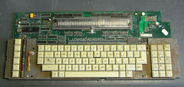
Joel gave me this keyboard a few years ago on the condition that I intend to do something interesting with it. That was an easy deal to accept.

Vintage computer keyboard assembly

Yellowed keycaps and lots of meta keys I’ve never seen before. Programmable function keys with a strip of LEDs next to them — and “lock” indicator LEDs carved right into the main keyboard keycaps. Onboard decoder logic and a 40-character 5×12-pixel vacuum fluorescent display. Does it get any better than this???

With the “PAR IND” key on the keypad, I have to admit that this was most likely from a word processing or typesetting machine. But I’d much rather believe it was removed from a Firefly-class transport ship.

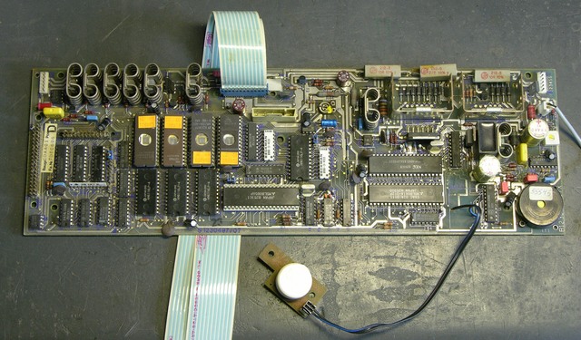
Circuit board from vintage computer keyboard assembly

I can’t figure out how this circuit board ties to the keyboard, but it’s purported to go along with it. The model number is in a similar style, the sticker includes the same “Baugr.” label, and the ICs were also (mostly) manufactured in 1981-1982, so it’s plausible.

So per our agreement, I do intend to do something interesting with this. In my book, reverse-engineering it and hooking it up as an operating keyboard (with onboard display) would be pretty interesting.

All I need is time . . .

Fixing an LED Sign

Sunday, March 1st, 2009

My wife is working a couple of evenings a week for a tax preparer who used to work for her when she was an H&R Block office manager. Friday night he was taking down his $300 sign out of the window to throw it away because it had a few dark LEDs. She told him no promises, but I might be able to fix it because I do stuff like that every night.

And yeah, she was right.

LED income tax sign with dark LEDs

I’m actually not sure I’ve seen all the failures the sign has to exhibit, but I’ve fixed two overt and two covert. The obvious ones were the dark LEDs in the white “M” and “E.”

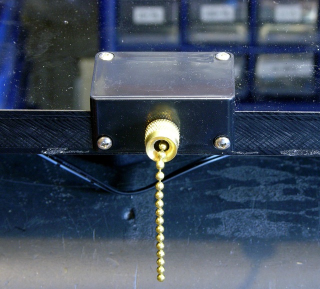
LED sign pull-chain switch

The less obvious ones were that the pull-chain switch at the bottom doesn’t shut the sign off, and that the DC power plug pops out of the jack.

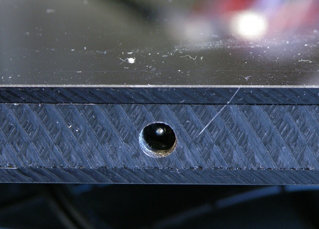
LED sign DC power jack, head-on view

Opening It Up

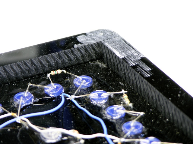
The sign is made of two plastic sheets sandwiching a thicker plastic frame. The front must be glued on, but the back is screwed on for repairability. Actually, given what the inside looks like, I have my doubts that the manufacturer ever considered repair; I suspect screwing the back on was just the first thing that occurred to them.

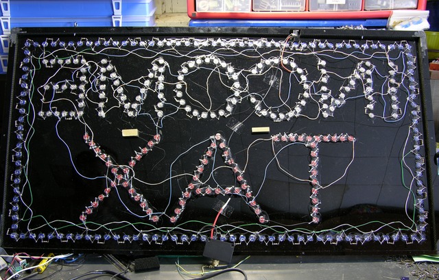
Interior wiring of LED sign

I’m (mostly) not knocking the schematic — many parallel series chains of LEDs is the only reasonable way to design something like this. And making chains of three each blue and white LEDs but five red LEDs is also reasonable, given the respective voltage drops.

But I do take issue with stacking three LEDs with 3V drops on a 9V (nominal) unregulated power supply. The supply happens to run about 9.7V under the load of the sign, which leaves .7V across the 150Ω current-limiting resistors, hence just under 5mA LED current.

Leaving that low a voltage drop across the resistors makes the LED current (and brightness) incredibly susceptible to variation in the actual voltage of the unregulated power supply: a power supply change from 9.7V to 10.4V seems insignificant but would double the (white and blue) LED current. Worse, a drop from 9.7V to 9.35V would halve it.

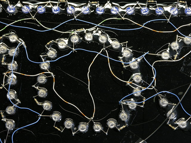
LED sign wiring closeup

Mainly, though, it strikes me odd that the sign is wired with leftover four-pair UTP (network cable). Was this thing built in some guy’s garage with stuff he pulled out of the dumpster at work? (Wait, did I build this thing??? ;-) )

Fixing the Power Connection

First things first — I started with the power connection so I wasn’t fighting it the whole time I was testing and repairing the rest of the sign.

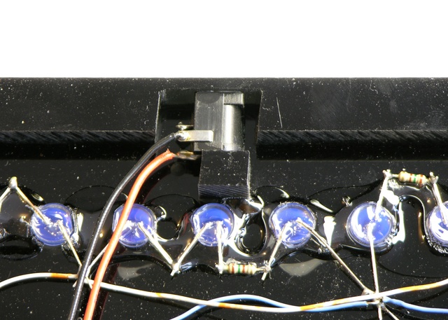
LED sign DC power jack, side view

The jack is recessed into the frame. The manufacturer made some effort to get it close to the outside and minimize the amount of recess; but the correct recess for this jack is zero. The plug is designed to make good mechanical contact when it’s sunk completely into the jack; before that point, the springiness of the jack’s outer contact pushes the plug back out of the jack, which is exactly what was happening.

LED sign DC power plug, cut to fit recessed jack

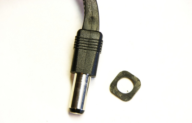
The solution, or I should say hack, was to remove a corresponding amount of rubber from the plug’s molded barrel insulation, so it could once again fit the depth of the jack properly. No further problems.

Dead LEDs

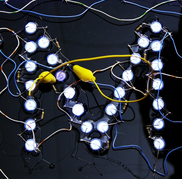
Next I tackled the dead LEDs. A series string of three was dark in the M, leading me to supect one LED burned out and open. Measuring the voltage drop across each, I found the entire ~9V drop across the uppermost LED, so it appeared to be open.

Jumpering across open series LED

After jumpering across the suspect LED, the other two in the string lit (of course, too brightly relative to their peers), so it was indeed open and the problem.

The right fix would be to replace the broken LED, but I don’t have any white 10mm LEDs on hand, it would take a while to order, frosted 10mm LEDs seem to be more difficult to find (or to find clearly specified as such), and I’d have to wade through long lists of nearly-identical products searching for the one that was actually right.

Immediately I thought of a way I could fix it using materials I had on hand — drill a hole into the back of the 10mm LED and sink a white 5mm LED into it. This idea made me cackle with glee, so you can imagine my disappointment upon realizing I don’t in fact have any white 5mm LEDs here. I need to get me some so I can go back and try that yet. :-)

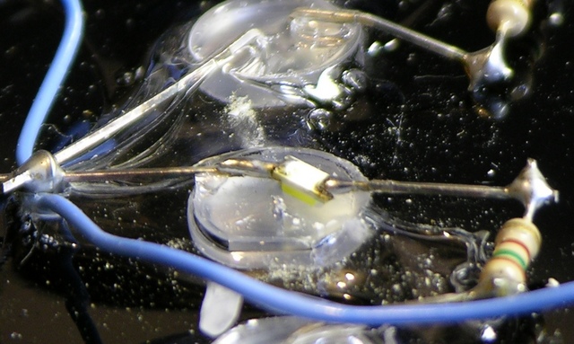
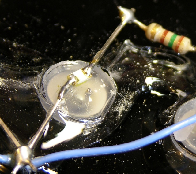
SMT LED soldered across burned-out 10mm LED

Really, this hack is just as good, though. (Ah, I realize I’m using the word “good” in a perhaps somewhat nontraditional sense.) The SMT LED soldered across the dead 10mm LED’s pins diffused nicely through the 10mm LED lens.

There was also one lonely dark LED in the “E.” Turned out when it failed, it didn’t open, so it was still passing current through for its friends.

SMT LED soldered onto burned-out 10mm LED

I used the same hack on this one, although I did clip one lead off so that the dead LED wouldn’t pull the voltage drop too low for my SMT LED.

I was surprised at how well the hacked LED in the “M” matched the brightness and color of the other white LEDs, given how different its physical construction is. The one in the “E” is a little more noticeable (picture down below), but probably not objectionable if you’re not specifically looking for it. And I’d say a replacement 10mm LED has fairly good odds of being a little off in color or brightness, too.

At 5mA I should have nothing to worry about; but I watched the first SMT LED with my infrared thermometer for a minute with the power on, and it didn’t get above ambient temperature. Should last a good long time.

“Fixing” the Power Switch

I got the pull-chain switch out of its housing and couldn’t see why it didn’t work. Since my wife said the owner leaves the sign on all the time anyway, I don’t reckon it’s worth replacing the switch, so I removed it and soldered in a bypass wire.

Because the switch was broken in the “on” setting, I could have left it installed and the sign would be on. But the switch is already broken, and who knows when it’ll further break “off” instead of “on.” Under the circumstances, I’d rather bypass it now than have to go back and reopen the case to replace the switch later.

LED sign empty pull-chain switch housing

There’s a sizeable cutout in the bottom edge of the back cover for the switch, so it wasn’t really an option to leave the switch cover off. It does look a little odd having the cover on there with no switch protruding, but it’s not awful.

Putting It All Together

LED income tax sign, repaired

And thar she be, in all her working glory. For the moment, anyway.

Shortly after taking that picture, I moved the sign and a couple of blue LEDs on the border went out; then one of them came back on. Half an hour later, both (all) were back on. I’m not sure I’ve seen the end of this yet, and I may have a sizeable job cleaning leads and resoldering cold joints sometime in my future.

Physical Construction

LED sign corner assembly

One last thing: the frame and skin construction of the sign forms a rudimentary torsion box. The plastic face and back are quite flimsy by themselves, and even the face with frame glued on was flexing as I was moving it. But the moment I got the back skin screwed on, the entire assembly was quite rigid and immune to flexing and racking. Pretty impressive for such a simple technique.