Thanks to nophead’s discovery that kapton tape makes a perfect ABS extrusion build surface, I knew that I wanted to cover my heated MakerBot CupCake build platform with it. While Scott was milling me a plate, I ordered a roll of 4″ kapton tape and a roll of 1″ double-stick kapton tape from eBay seller mn-vac, whom I can’t recommend highly enough. He had some long-running auctions that he had updated to indicate that he was out of town and wouldn’t be able to ship for a couple of weeks, but still responded immediately to my questions and had the package shipped to me well before he was even scheduled to return.
I had my acrylic insulator from Ponoko that press-fits perfectly onto the Y stage and the aluminum plate from Scott.
Scott had even milled a recess into the underside of the plate for the SMT thermistor Tom put onto the heater PC board; but because I wasn’t sure exactly what other features would need recesses and where, Scott left them for us to mill.
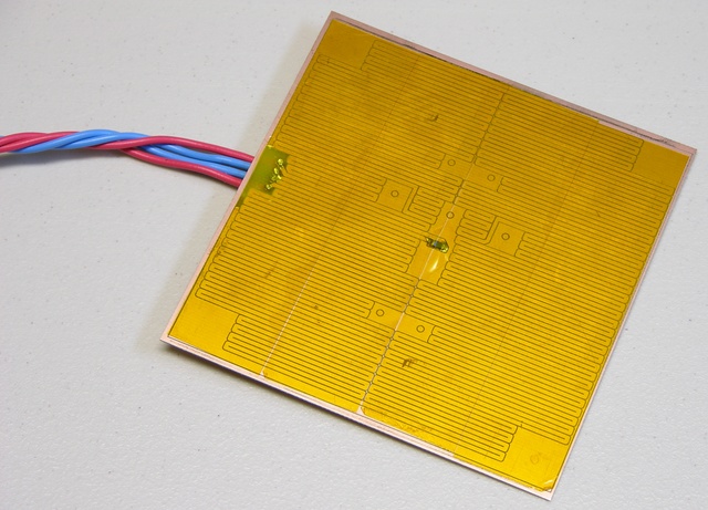
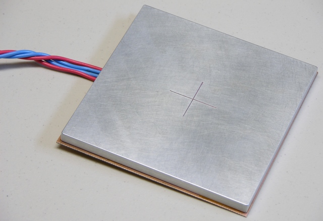
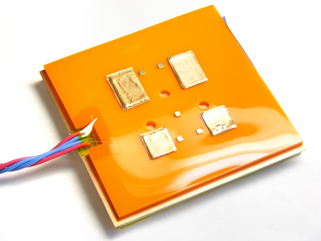
Two weeks ago Tom and I finally got together to assemble the heater, aluminum plate, and insulator into a tasty heater sandwich.
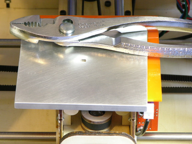
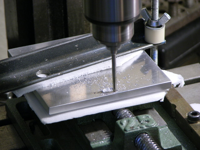
First I marked on the aluminum the location where the wires would connect to the PCB. Tom milled a recess into the aluminum to provide clearance for the solder joints on the top side of the PCB.
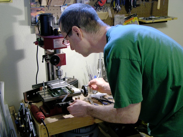
Tom did quite a nice job of milling a trapezoidal recess by hand without any CNC assistance, and was careful to protect the surfaces of my milled plate.
Tom soldered wires to the heater PCB. After confirming that the heater resistance was still about 4Ω at the far end of the leads (the same as the resistance of the heater trace on the board) to make sure we hadn’t shorted anything, we covered the PCB with double-stick kapton tape.
The PCB was slightly oversized, so I had fit the pieces together first to mark the correct alignment. I set one edge of the aluminum into place on the double-stick tape, leaned it down and rechecked alignment against my marks, then pressed it into place.
Besides holding the pieces together, the tape insulates the PCB traces and the thermistor from shorting on the aluminum. We re-measured the heater resistance at 4Ω just to be sure we hadn’t shorted anywhere.
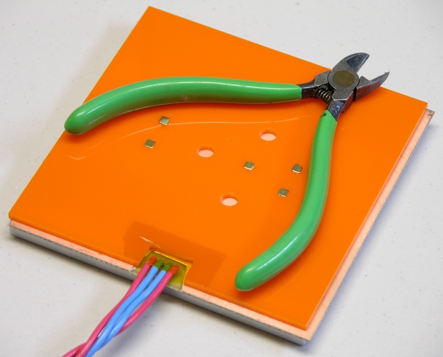
While Tom was milling the aluminum, I had marked, cut, and filed a notch in the acrylic to route the wires out the back of the heater assembly.
We attached the acrylic to the sandwich in similar fashion and put a little piece of kapton over the wire recess, more for show than because it actually provides much holding power. I could fill the recess with a heat-safe gasket compound, but the wires have been doing okay so far and I like knowing I can disassemble this for repair or upgrade.
Note how Tom peeled the copper off the back side of the PCB around the wires’ through-holes.
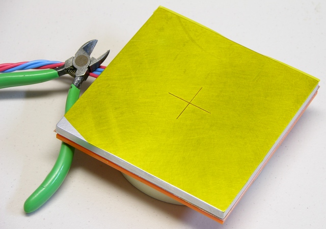
I hadn’t realized how difficult it would be to apply 4″-wide tape to a square platform. The 1-mil tape is really schlimmery and hard to align straight where it first touches and grabs onto the aluminum, hard to squeegee down without bubbles, hard to press down straight without creating wrinkles, etc. I’m pretty good at squeegeeing screen protectors onto PDAs straight and bubble-free using a credit card, but the kapton tape was having none of that. An edge of the tape also tore coming off the roll. (It looked like it was bunched up where it had been sheared at the factory.)
Oh, and it didn’t help that the aluminum was still hot from a test firing and Tom and I were both halfway juggling it trying to hold it and the tape. ![]()
Printing on the Heated Platform
Many folks building heated build platforms are powering them from the extruder and hacking the firmware to control the platform temperature. I’m not averse to this idea in the long run; but for expedience, I brought a variable power supply and we used it to power the new heater.
Tom ran the supply up to about 24V to heat the platform quickly and then dropped it back to 12V to maintain a fairly steady temperature somewhere in the 180-200°F range. (It wasn’t varying that much; I just don’t remember exactly where Tom set it.) The power supply’s current meter showed a reassuring V / 4Ω the whole time.
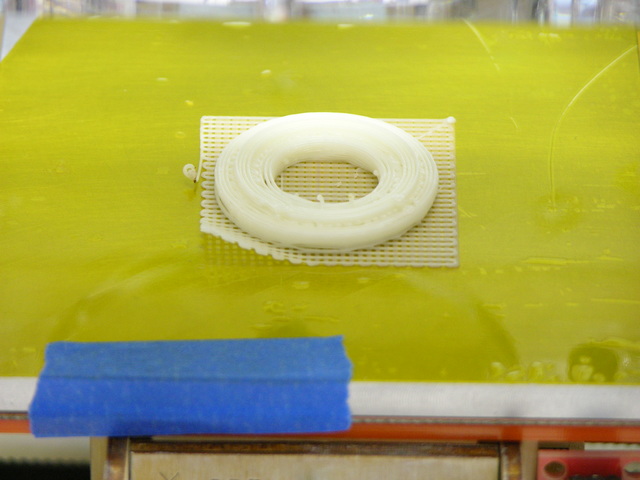
The first printing attempt was Zach’s idler pulley. I have other settings wrong (the perimeter density is too low), but the raft adhered perfectly to the kapton. The lifted corner is where I started to peel up the still-pliable ABS without having let the platform cool quite enough.
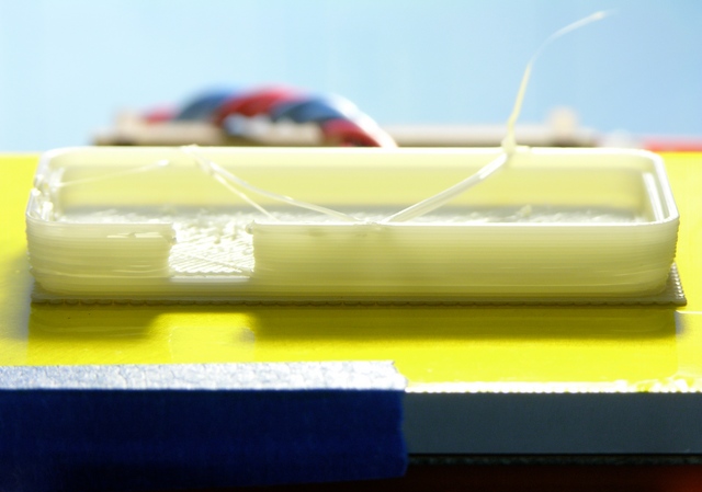
Tom added the blue tape, by the way, to create a non-specular surface for the IR thermometer we were using.
Skeinforge had some wacky ideas and my densities were off again, but a fob case built perfectly flat with no lifting or warping as well. I let the fob cool longer than I had the pulley before trying to remove it, and it popped right off the kapton with only slight deformation in the corner where I wedged the knife blade (still too soon).
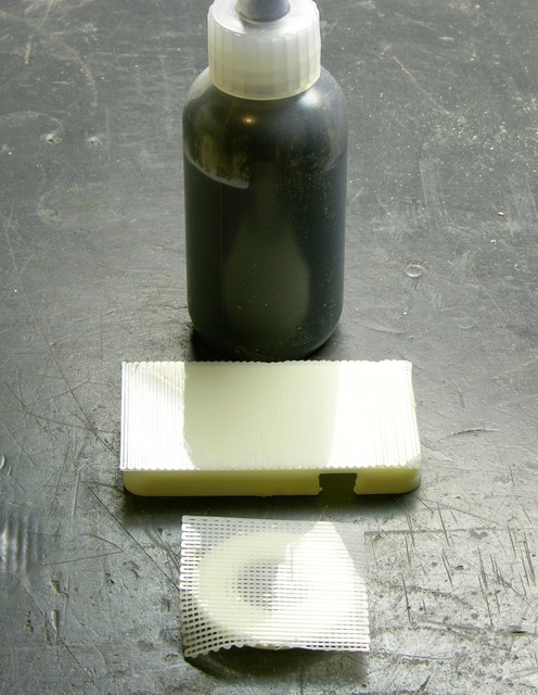
As nophead did on his initial tests, I got delightfully smooth and reflective surfaces where the ABS conformed to the hot kapton.
Next Steps
Living in Times of Raft-Free Printing
As zaggo described in Living in Times of Warp-Free Printing, I no longer need to print a raft under my builds. I’ve not yet installed the Skeinforge Raftless module, which prints a leader into the first layer to give you time to fine-tune the nozzle height (and amount of extrusion squish) and slows down the feed rate of the first layer to help smoosh it onto the platform. But with judicious live Z-axis tweaking, I’m getting reasonably good results.
Flatness and Leveling
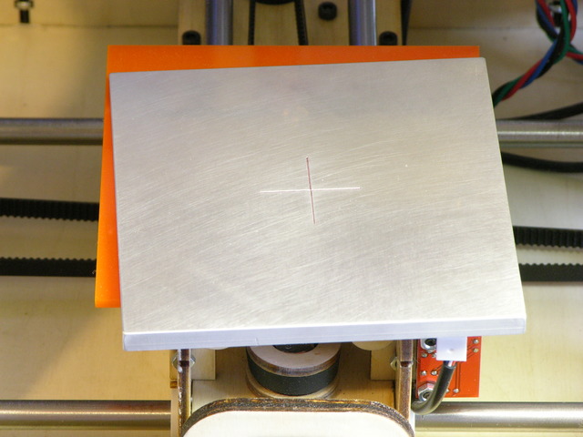
The aluminum plate appears to be dead flat, as it should be (and as I had hoped). It is not, however, dead level with (parallel to) the X and Y axes, causing the first layer of large objects to be tightly smooshed at one edge and not quite sticking to the platform at the other edge.
Tom and I stacked copper tape scraps on the underside of the platform in a quick and dirty attempt to level it, but the copper tape appears to be just squishy enough that it probably won’t provide reliable leveling.
Worse, you can see that the heater gets a bit too warm for the acrylic and my “insulator” is starting to warp after only a few hours of use. I’ll need to add a sheet of real insulating material between the heater PCB and what I believe I shall rename the acrylic “mounting plate.”
Also the left edge of the Y stage plywood is not fastened down to the walls, so there’s more play in the height / level of the left edge there. I’ll probably glue that together to make it rigid enough to use as a good base.
I’m thinking that nylon set screws in miniature T-nuts set into the Y stage may be the best way to level the platform. There’s not a lot of room to spare in the Y stage; I may have to cut a larger, replacement stage top. (Ponoko again.)
Thermistor, Power Supply, and Enclosure
I had assumed I’d use the thermistor for closed-loop feedback, but at Tom’s house 12V seemed like the perfect supply to keep the plate at the desired temperature and I considered wiring it straight to the PC power supply.
Since then I’ve used it in my colder utility room and had to turn the supply higher than 12V to get the plate warm enough. That suggests both that I will need to use the thermistor and that the CupCake’s PC power supply may not be an adequate power source for this heater. We may need to make a second PCB heater with slightly lower resistance — although I’m leery of increasing the heater current too much, lest the lead wires start heating up too.
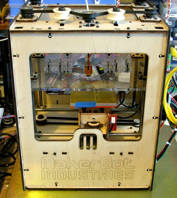
Alternatively, rather than cranking up the power, I’m considering making plexiglass doors or panels to cover the CupCake’s openings and retain more of the heat from the platform. It seems like a more efficient approach; and it would also help warm the whole chamber, which should further reduce warping on objects that are both tall and wide.
Even though the extruder pokes through the top of the CupCake when at its highest elevation, quite a bit of the CupCake top could still be enclosed — and the Z platform itself nearly spans the CupCake interior, helping trap heat in the part of the chamber containing the heated platform and the extruded model. Again a good thing.
you could use a nylon oven bag to cover the top hole. (turkey bag)
i’m leveling my heated bed with kapton tape.
What mill were you using to make the aluminum bed?
Tyler, a friend milled the crosshair into it on a Sherline and the pocket for the solder joints was done on the Central Machinery drill press in the photo. The marks on the surface are just sanding marks, as I recall.