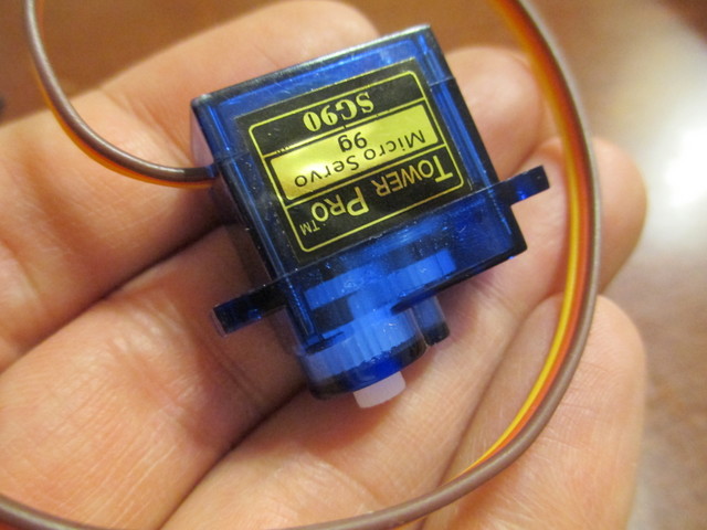
A common strategy in the world of hobby robotics is to modify a servo for continuous rotation to use to drive the wheels of a tabletop robot.
On its own, the servo takes power, ground, and a position input and moves the shaft within a range of rotation to match the angle requested on its input wire. It has one or more stops in its gearbox to prevent it from rotating past the end of its range; these need to be removed. It also has a potentiometer as part of its positioning system, which — for the usual modification — needs to be tricked into thinking it’s always centered. The modified servo then runs at full speed forward or backward trying to reach a requested position and thinking it has never succeeded in doing so; and the controller requires extra, external rotation sensing if you want to detect what the servo has actually done so far.
I wanted something a little different — PWM H-bridge control of the servo’s motor for variable speed forward and backward and access to the potentiometer to detect position (crudely and at low speed) and count wheel rotations (acceptably and at high speed). This is actually an easier modification — but, though I’m surely not the first to do it, I’ve not run across it before. I started last night.
The cute little SG90 has four screws holding its case together.
After removing them, the base can be pulled off, revealing the back of the motor and the back of the control board.
With the control board pulled out, it’s easy to see that the motor and potentiometer are wired exactly as would be expected; and nicely color-coded, making it easy to see how to rewire the servo.
The top of the case also pops off to reveal the gearbox. The output shaft is in the lower right and the two nubs on the back side of the output gear are the stop that prevents continuous rotation. I snipped them off in place using a very sharp diagonal cutter.
Next steps: Select wiring harnesses and rewire the motor and potentiometer.


The first time I saw this was in the late 90′s for the original ChiaBot minibots (http://battlebots.wikia.com/wiki/Chiabot). They each had two modified servos and two wheels. A standard RC controller drove them around with tank-style steering. It’s a great hack!
I’ve always enjoyed your blog, glad to see a post. Hope the new year treats you well.
I did something similar with a HiTec servo for a robotics project (also for a robot). It seemed to work very well. I notice you’re using a micro servo. Will these same methods work for other servos as well?