Archive for the ‘Repairs’ Category

Refitting a Strain Relief

Monday, July 21st, 2008

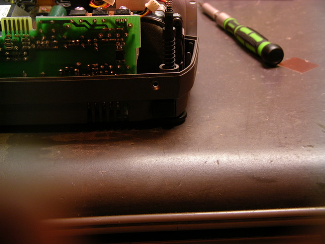
My dad had a break in the power cord of his hair clipper, right next to the strain relief. That should be ironic, except I already know most strain reliefs are too stiff and just move the site of cable stress rather than relieve it. I guess that makes it ironic but expected.

At any rate, the strain relief was molded onto the cable, so the cord wouldn’t just slip out for repair; and the break was so close he didn’t know quite how to splice it back together; and he asked me to fix it for him.

Hair clipper strain relief with broken power cord

At first all I could think of was hideous things like replace the strain relief with a grommet and a huge wad of hot glue. But I let it sit for a day, and realized that the much easier solution would also be both cosmetically and functionally superior.

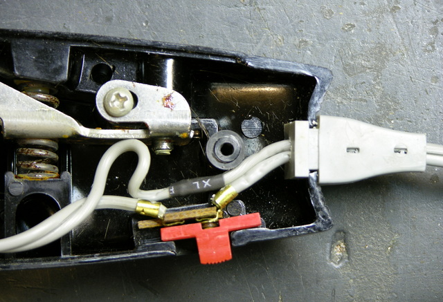
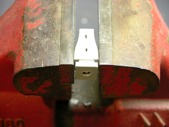
I cut off the power cord flush against the inner and outer ends of the strain relief, then drilled the power cord out of the center of the strain relief with progressively larger bits until the hole was large enough to push the cord through again. Super simple, and it leaves a very finished appearance — you can only tell it was repaired if you look closely.

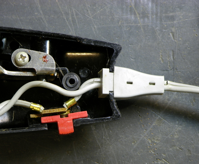
It’s more obvious if you look inside, of course. The extra loop on the long wire really shouldn’t be there. I had both wires cut to the same length and spliced, and then the original short leg popped loose of the switch’s crimp connection and it seemed more practical to cut off the splice and fit the new end straight into the crimp. By then I didn’t feel like reopening and resoldering the long connection, so I just mushed it in and let it be.

Good enough.

Repairing an InFocus LP290 Projector, Part 2

Thursday, May 8th, 2008

Last fall I bought a used InFocus LP290 projector, and in January I opened it up and found that the polarizing filter for the blue LCD was melted. Since then I’ve been keeping an eye out for a replacement filter, and Monday night I parted out a dead Optoma projector from Jeremy for the polarizers. Tonight I fitted one to the InFocus, with surprising success.

LCDs and Polarizing Filters

A long time ago, I think I knew how LCDs work, but I’d forgotten until a great conversation I had with Dave, who posts comments here from time to time and is immensely knowledgeable about LCDs. To paraphrase:

In high school physics, we learn that light behaves as both particles and waves (both of which can be demonstrated experimentally). In the wave model, light is a transverse wave: it “wiggles” from side to side in a plane containing its line of travel. (In contrast, sound is a longitudinal wave — it makes compressions and rarefactions back and forth only within the line of travel.)

Normal light has waves wiggling in all directions around the line of travel — up and down, side to side, and all angles in between. A polarizing filter only lets through light waves wiggling in one particular orientation, say up and down. It also lets through the up-and-down component of waves wiggling at an angle other than up and down; but waves wiggle side to side have zero up-and-down component and get completely block.

Digression: polarizing filters are used in photography and in sunglasses to block glare. It turns out that the light waves in certain kinds of glare have been polarized by their reflection off the surface of whatever object is glaring, and polarizing filters can completely block those types of glare. It’s a really cool effect to rotate a polarizing filter in front of something that’s backlit at a fairly steep angle and watch the glare appear and disappear.


I have this description backwards. See Dave’s comment for an excellent description of how it really works.

Back to LCDs: the crystals in LCDs pass light waves untouched when they’re inactive, and twist the polar orientation of light waves when active. This is the key to how LCDs work.

An LCD screen like on a cheap calculator has a polarizing filter in front, the LCD panel, and a backing mirror. Light from the room hits the filter and only the portion in the proper orientation (say up and down) passes through. That light then passes through the LCD, and where the LCD is inactive the light maintains the same orientation. It reflects off the back, passes through the LCD untouched again, and is already in the correct orientation to pass through the polarizing filter on the way out. Thus where the LCD is inactive, you see light areas.

Where the LCD is active, it twists the polarization of the light waves by 45°. (There are other possibilities, but I’m talking about simple and cheap.) It reflects off the mirrored back and passes through the LCD again, getting another 45° of twist for a total of 90° with respect to the polarizing filter. That’s exactly the angle of polarization that’s completely blocked; so where the LCD is active, you see dark areas.

In projectors, with light passing through the LCD only once, it has to work a little differently. I’m guessing the LCD does 90° of twist, with polarizing filters both before and after.


So without the “before” polarizing filter in the blue light path of my projector, the darkest the blue beam could ever be was about medium-bright, because it only got half as filtered as it was supposed to. Instead of true blacks, I got medium blues. White was still white, of course, because that’s where the light was supposed to pass through (and still did).

Colored Polarizing Filters

Looking at the optics inside projectors, there are lots of things reflecting, refracting, and filtering light, and I often see color tints and have trouble determining which thing I see is the color filter. So after taking the first polarizing filter off the Optoma and finding it to be a dark blue-grey, I thought it was a neutral grey and didn’t think any further about color.

Tonight I found that each polarizing filter is a different color, complemenrary to the color of the light path it’s installed in. I was having trouble figuring out why you’d want to have a color filter and a polarizer. Since the yellow-orange filter blocks blue light in the blue beam, it seemed it would simply dim the blue beam all around. Okay, that leads to blacker blacks; but (apparently) in the same way as just using a dimmer bulb. That didn’t make any sense.

Then I looked through the colored polarizing filter more carefully.
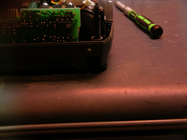
Desk viewed through orange polarizing filter from projector, sideways

Desk viewed through orange polarizing filter from projector, vertical

The two pictures are taken with the same camera settings, the first with the orangey filter held in front of the lens horizontally, the second vertically.

Both pictures have the orangey cast to them, but notice in particular the color of the glare on the edge of my desk. In the second picture, it’s nearly white, not orangey like everything else. That’s where the glare is.

I believe this filter passes all colors of light in general, and specifically blocks blue light that has opposing polarization. That’s why the screwdriver looks about the same in both pictures — everything except blue gets through, and the light from the screwdriver isn’t polarized so the blue is blocked. The glare on the edge of the desk is polarized, so even the blue gets through and gives a more even white.

That’s kinda cool. And that means the filter should do an extra good job of darkening blues where the LCD is active. With a complementary-colored filter in each of the three color beams, it means it should do a really good job of making black blacks.

Fitting the Filter to the Projector

The InFocus and Optoma obviously don’t use the same size filters, as the Optoma filter clearly doesn’t fit the InFocus carrier. Fortunately, the Optoma filter is larger, so at least I can hack it to work.
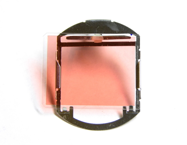
Projector polarizing filter fitted into different carrier

(The camera doesn’t represent the filter color very well, by the way. In real life, it looks very similar to the deep orangey-yellow of yellow liquid food coloring, not as pink as it looks here.)

I confirmed the proper orientation for the filter by very carefully slipping it into position in the projector and holding it there with a needlenose pliers with the projector running, and the proper orientation is horizontal. Too bad, since the Optoma filter was as tall (short dimension) as the InFocus carrier is wide (long dimension), and it actually fit really well in the carrier the wrong way.

But with a little bending of the carrier edges, I got the too-large filter secured in (and hanging out of) the carrier well enough to reassemble the projector. The glass isn’t parallel to the carrier any more, but I can’t think of any reason that’ll make a difference. You can see the glass slide sticking too far to the left, and slanting forward, in this picture, between the silver carrier mounting tab above and the LCD housing below.
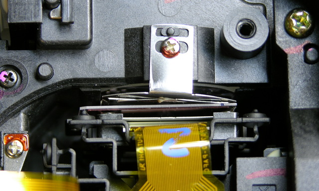
Hacked polarizing filter installed in projector

The projector works now, and the blacks are black again! I’m not ready to close it up and call it done until I sit next to the projector and test it for an evening to make sure it’s not going to melt down and light my house on fire, but I’m optimistic. And if it works, I’ll think about cutting down the glass the filter is mounted to, so it fits properly.
Parting Out an Optoma EzPro 610H Projector

Monday, May 5th, 2008

I just disassembled a dead Optoma EzPro 610H projector from Jeremy, to look for a polarizing filter to fix my InFocus LP290 and see if Marsh Ray can fix a Sony VPL-PX15. The filters from the Optoma look to be about the right size for my InFocus, so I’m excited to think I may be able to get it working again 100%.

Meanwhile, I ended up with a whole bunch of parts I don’t need, some of which might be useful for repairing other EzPro projectors. I’d like to offer these to anyone who could use them, for whatever you think they’re worth plus the cost of shipping. If you’re interested in any of these, see below for instructions.


Update 06-May

Jeremy says:

Had power indicator lights, but bulb would not light. Replaced bulb, same deal.

So the problem is likely in one of the logic boards (microprocessor not responding to sensors that say it’s okay to power up the lamp) or power supply boards.


Available Parts

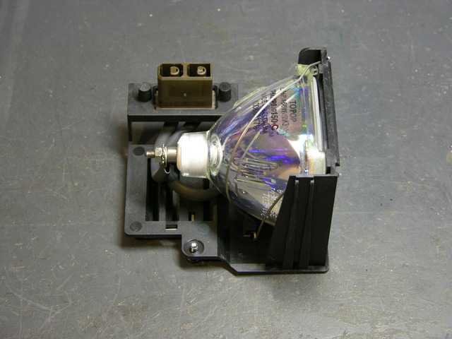
Projector lamp

Projector lamp. Sold. I don’t know whether it works, I don’t know how many hours of use it has, and I don’t have any way to test it. I believe lamp failure is not what killed the projector.

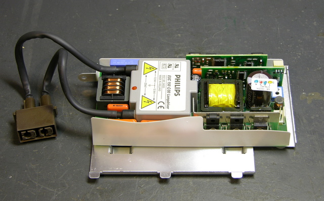
Projector lamp power supply

Lamp power supply. I don’t know whether it’s good and I don’t have any way to test it; but it’s modular enough, if you suspect it’s what’s wrong with your projector, it’s worth trying.
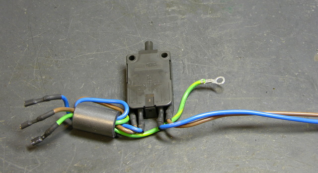
Interlock switch

Lamp service panel interlock switch. Not very exciting . . . but handy if, um, mice have been living inside your projector.

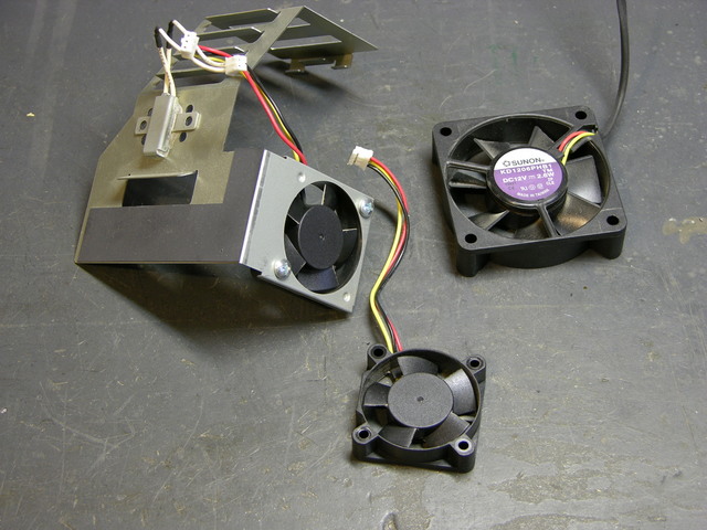
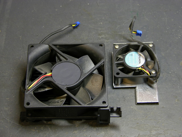
Three projector cooling fans

Three cooling fans that mounted to the optical housing: rear left, right, and bottom.

Two projector cooling fans

Two cooling fans that mounted to the case: bottom and front.

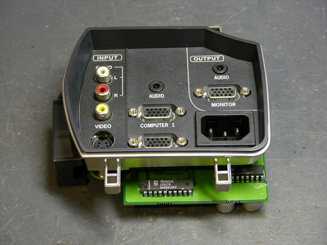
Projector input panel

Video input panel and associated PCBs.

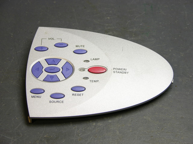
Projector control panel

Top control panel and attached PCB.

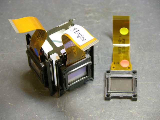
Projector LCD panels

All three LCDs are available, removed from the prismatic lens thinger on the left and without polarizing filters. I removed the red LCD (right) from its mounting frame (further disassembled than it is here) before I found where the polarizing filter was (elsewhere), so it needs some RTV reapplied to hold it firmly in its frame. This will be obvious upon inspection.

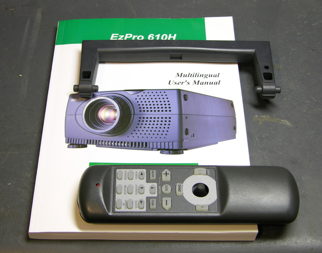
Projector book, handle, and remote control

Owner’s manual. Sold. Carrying handle. Remote control that looks slightly different than what’s in the book but has the same part number. Sold.

NOT Available Parts

I’m NOT giving out the following, so don’t even ask:

  • Any of the optics. I think they’re unlikely to be damaged in anyone else’s projector, I think they’d be difficult to replace and realign successfully if they were damaged, and I think they’re kinda cool to hang onto.
  • The projector’s main board and main power supply board. I think they’re too likely to have been the source of the problem with this projector, and I’m just going to harvest them for components.
  • The last polarizing filter. I’m going to hang onto it for a rainy day.

How to Make a Request

If you’re interested in anything from here, post a comment below indicating what you want, what it’s worth to you, and what your ZIP code is. Make sure you enter your email address correctly on the comment form, because that’s how I’m going to contact you.

Then add my email address, neufeld at this domain, to your address book or whitelist. Because I have an unusual domain name and because I run my own email server, a lot of email from me ends up in people’s spam folders. I will only email you once. If you want something from me, make sure you receive that email.

I’ll contact you shortly to let you know whether I still have the item, and how much shipping will cost. You PayPal me the cost of shipping only, and I’ll send you the item. When you get it, if it works, you PayPal me whatever you think it’s worth. If it doesn’t work, you send it back at your expense and I’ll add it to my junk pile.

Repairing Alesis M1 Active mk2 Monitor Speakers

Wednesday, April 30th, 2008

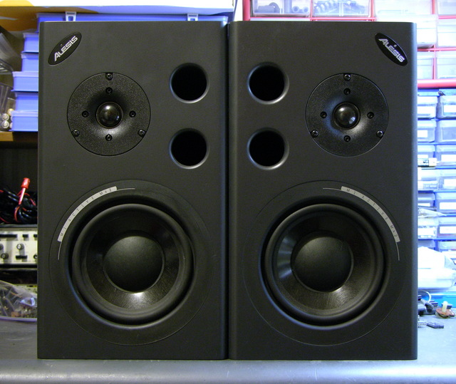
For Friday’s show, we used Alesis monitor speakers that we had in the lab, plus Steve, one of the students, supplied two.

Alesis M1 Active mk2 speakers

During installation, one of the speakers started winking its blue power light and ceased playing sound, and before the show another did as well. Steve found a Studio Central forum post suggesting that the problem was due to a failed electrolytic capacitor that gets baked by a hot resistor right next to it, and a quick peek inside confirmed that it was a likely explanation and fix.

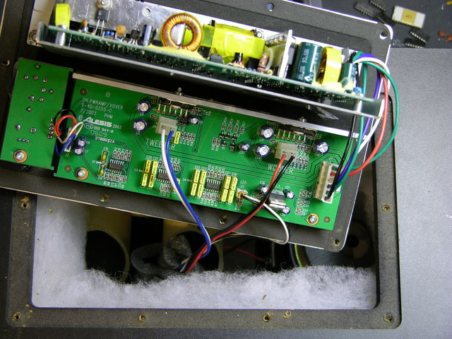
Alesis M1 Active mk2 speaker, circuit boards and interior

After unscrewing, the back panel lifts out and reveals the power supply board mounted vertically on a metal shield, and the crossover/amplifier board mounted flat on the panel.

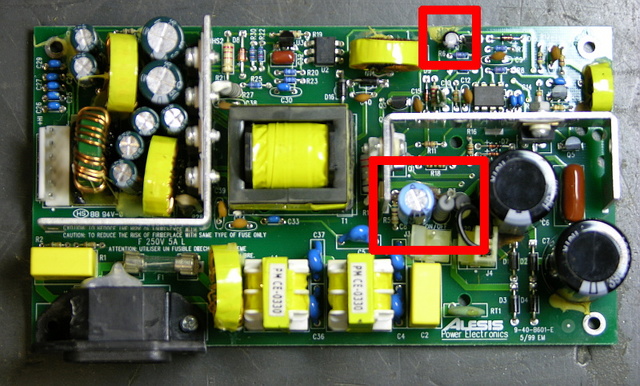
Alesis M1 Active mk2 speaker power supply board

The naughty capacitor, C8 (actually its replacement after I finished), is in the center red rectangle next to the offending resistor. Another bad electrolytic capacitor whose number I forgot to catch is featured near the top of the board. Both of these tested bad with my Capacitor Wizard in-circuit equivalent series resistance (ESR) tester; all of the other electrolytics on the board tested good.

It was simple work to remove and replace the two capacitors on each board, and it brought both speakers back to life. Thank you, forum posts and Capacitor Wizard!

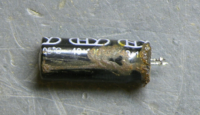
BTW, are electrolytics supposed to look like this?

Leaky electrolytic capacitor

Two caveats about this repair. First, I should have used 105°C capacitors, but I could only find 85°C caps on short notice, so these will fail quickly and need to be replaced again. At least now it’s known exactly what needs to be done. And second, the forum post suggests moving either the resistor or capacitor to get them further apart, which is a great idea but which I haven’t done yet. I’ve been trying to think up a clever way to stick a little heatsink on a vertically-mounted resistor, which might be a better solution yet.

Repairing an InFocus LP290 Projector, Part 1

Sunday, January 13th, 2008

A few months ago, I bought an InFocus video projector on eBay, still hoping to watch movies on the wall of the family room. It’s about 1/12 the size of the behemoth Sony projector I was trying to repair earlier, and quite a bit sharper and brighter; so if I can get it going, it’ll be a nice replacement.

When I received it, I immediately noted two problems: It shuts itself off after anywhere from seconds to hours; and it has a yellow silhouette running up the middle of the picture, kind of like the face/vase illusion.

I’ve taken some time this afternoon to disassemble and diagnose the projector; so although it’s not fixed yet, here’s what I know so far.

Chasing the Yellow Blob

In which Keith removes Crusty Gummy and washes a filter carrier

From the looks of it, I was pretty sure that the blob was going to be something wrong with, or wrong on the surface of, one of the lenses, mirrors, or filters. Yes, it looked a little like an LCD ruined by being left in a freezing car overnight, but not quite. So I dug in to follow the light path through the projector and see if it would be apparent what was wrong.

After popping the cover and removing the main circuit board, I could see most of the periscope-like light enclosure. I removed a couple of lenses that dropped in from above, which were clean, and looked at a couple of mirrors, which were also clean. The next thing I wanted to check was the LCDs.

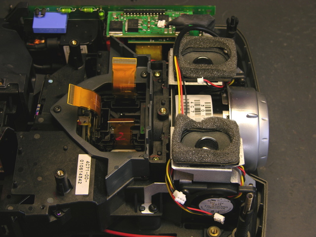
Interior of InFocus LP290 Projector

In order to get to them, I had to take off the collar above/around them, remove the two cooling fan / speaker assemblies, and remove the main lens. The LCDs were mounted to the lens carrier and looked fine; their removal left access to this cavity where the RGB light paths converge.

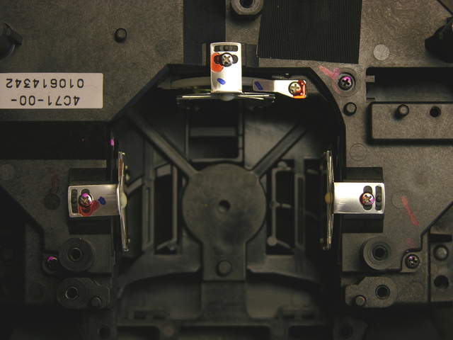
LCD cavity on InFocus LP290 projector

I didn’t notice it until later, but someone had already been here before. Loctite on the RG screw tabs and missing from the B tab.

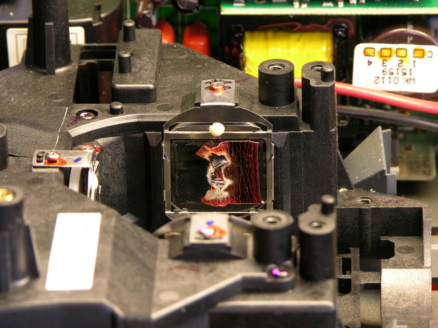
From a different angle, the problem was obvious.

Melted polarizing filter from InFocus LP290 projector

The filter between the blue light path and the blue LCD is all melty. Bad.

First things first. I gently peeled off the Bad, scrubbed all the goo off the glass carrier with Goo Gone, washed all the Goo Gone off with Dawn, rinsed the Dawn off with water, and dried the water off with a paper towel. (Life is sooooo complicated.)

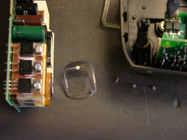
Cleaned polarizing filter carrier from InFocus LP290 projector

Here it is all shiny and ready for . . . whatever comes next.

While I was in there, I detached and examined the other two filters. They didn’t look colored, just a light neutral grey in a very familiar sort of way. Apparently the filter isn’t what makes the blue blue (that’s the blue half-mirror further upstream), so maybe I can just put it back together and see what happens.

Reinstalling the Filter Carrier

Assembly is the reverse of disassembly.

The projector is back together and emitting blue light when it should be emitting black. The Bad was the polarizing filter that makes the LCD do its thing, so I’m going to have to find another one and put it back. It’s still emitting shades of blue; it just puts out quite a bit of blue when it should be going all the way to black.

I’d welcome donation of a spare polarizing filter from a differently-ruined LP290, and I’m shopping for a broken one. But partly for sheer “I can’t believe you did that and I can’t believe you got it to work” value, I’m sorely tempted to get a polarizing filter somewhere else and see whether it’ll do the job. Like a photographic filter. Or an LCD from dead equipment. Or sunglasses. :-)

Of course, none of those are good ideas. It obviously gets hot inside the projector, and meltage problems are going to avalanche as the filter warps and discolors and becomes less transparent and absorbs more energy from the light and heats up and warps and discolors. So I’ll at least look around for a spare projector to cannibalize.

Power Supplies

The projector has the lamp cover interlock switch and AC-DC power supply on the starboard side and the DC-DC power supply and lamp ballast on the port side. The AC-DC supply is always on, and the DC-DC supply appears to be under control of the microprocessor that runs the soft power button and monitors the sensors scattered throughout the projector.

The AC-DC power supply checks out okay, as far as I can tell. All of the electrolytics test good with my Capacitor Wizard, and the three voltages (16.5V, 6.6V, and 3.3V) are present on the edge connector that plugs into the main board.

I took the projector parts over to Ron Tozier, and he suggested testing all the voltages with the projector in standby, with the projector on, and after the projector shuts itself off. That should help determine whether the failure is in the AC-DC power supply board (probably not), in the DC-DC board, or quite possibly with one of the sensors. He also noticed that the main board has nicely labelled test points for lots of voltages, including not only the raw AC-DC supply outputs but also regulated and switched voltages under microprocessor control.

I printed out a digital pic of the main board, highlighted all the power supply test points and wrote the standby and on voltages next to them, and am now waiting for the projector to shut itself off. Of course it would pick now to stay on for hours.

I do note that every time I turn it on, as it powers up the lamp, I hear a chittering sound like an ultra-high-pitched buzzing. I think it’s the ballast going out, and I’m pretty sure the projector would sense a ballast failure and shut itself down. So I suspect I have a pretty good idea what I’m going to find is causing that problem as well.

Fixing a Kids’ Educational Toy

Sunday, January 13th, 2008

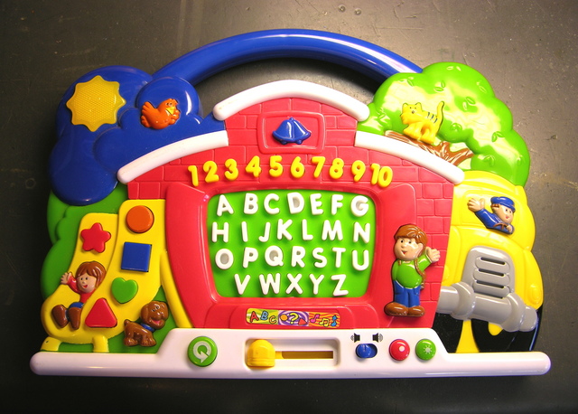
Alphabet training toy

A while back, my wife got this alphabet-training toy for one of our nephews. When they opened it and tried it, it “didn’t work and the batteries got hot.” Sounded like a short to me, so I figured I’d take a look.

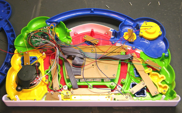
Alphabet training toy, interior

The inside was interesting — I wasn’t expecting a bunch of little pushbutton circuit boards and a ton of fly wires (bundled together with cellophane tape), but I guess it makes sense. In China skilled labor is cheaper than automation, so a bunch of little boards with hand-soldered wires probably cost less than one big board made by a machine.

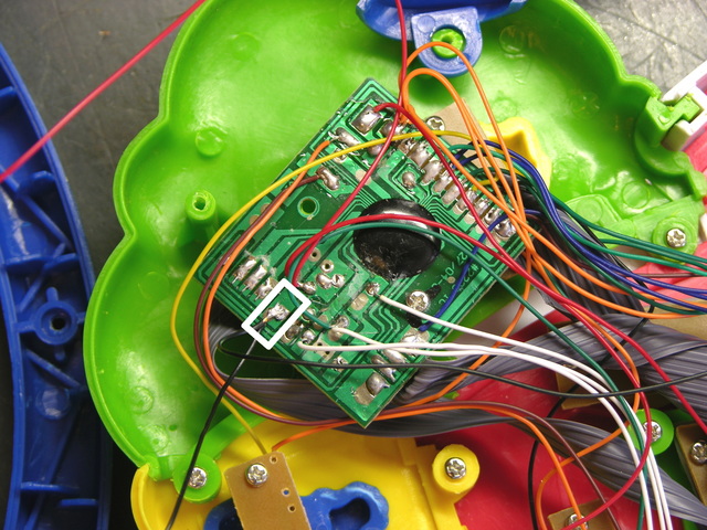
Alphabet training toy main circuit board

I put my meter across the terminals of the (empty) battery compartment and measured 0Ω — a dead short. I visually inspected every connection on the main PCB, assuming I’d find a solder bridge, but I didn’t. I desoldered the battery and power LED ground wires from the PCB (outlined in the white rectangle) so I could start isolating the short, and the short went away.

Let me say that again: I measured across the battery terminals (with the ground wire disconnected from the circuit) and got no short, as expected. I measured across the LED and got no short. I measured from the ground pad on the PCB to the positive terminal and got no short. I reattached the ground wires, still had no short, and the toy powered on and worked.

I’m quite certain I didn’t fix a solder bridge at the ground pad. My best guess is that while I was moving all the other wires to make room to work, I pulled apart something that was making contact and shouldn’t have been. But it’s quite a mystery what I really did that fixed it.

Except for the Batteries

Except for the batteries, which weren’t making reliable contact.

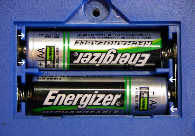
Kids' toy battery compartment

The shoulders of the cell compartments were too thick for the positive ends of several different brands of AA cells to make contact with their . .  uh, contacts. So I sharpened up my best $3 wood chisel (the one that I use to pry up leads on circuit boards I want to desolder) and shaved them down, and now the batteries make great contact.

But It’s Too Late

My wife says the nephew has outgrown the toy, so it won’t go to him. We have a couple of nieces about the right age, so one of them might get it, or she might take it to a thrift store.

Replacing My Visor Prism’s Battery

Monday, November 19th, 2007

I still use my Handspring Visor Prism PDA for my calendar, contacts, and some notes and lists. I like the Windows version of the Palm Desktop better than any other calendaring application I’ve seen (way better than iCal), which results in my having a low-end PC under my desk running Palm Desktop, and Synergy to use one keyboard and mouse across my two Mac monitors and one Windows monitor. And I like the color Visor Prism better than my original greyscale Visor because the white backlight makes the screen easier to read than black on grey-green.

The Prism was the first Handspring product to contain an internal, rechargeable Li-Ion battery; and my battery life has dropped over the last five years from weeks of standby / well over an hour of use to a couple of days of standby / a few minutes of use.

I found a replacement battery on eBay for $5.95 plus shipping from enessysales, whom I can heartily recommend. I bought and paid for my battery Thursday and received it tonight (Monday) via USPS. These folks are on the ball.

Battery Replacement

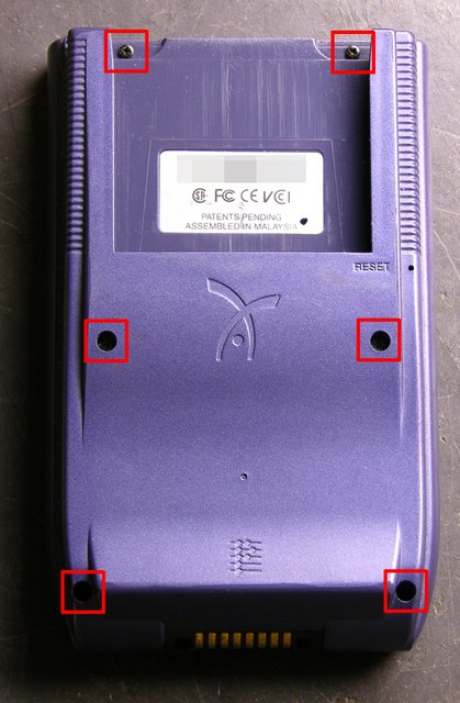
I have a tendency to open things to see what’s inside; but strangely, I had never opened the Prism before. As it turns out, battery replacement was straightforward. Remove the six Phillips screws:

Visor Prism, six screws for disassembly

Then gently pry apart the sides with a thumbnail. With the screen facing down, fold the Visor open on the right, with the speaker and battery leads trailing across.

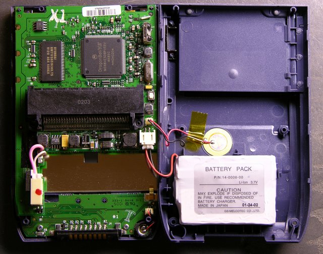
Visor Prism interior

The battery is fastened to the back cover with double-stick foam; so pry it loose, then disconnect the plug.

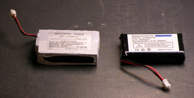
Visor Prism original and replacement batteries

The replacement battery is smaller than the original, but at 1600 mAh, I believe higher capacity. The original battery is also now stuck to my desk with double-stick foam. Errrrr.

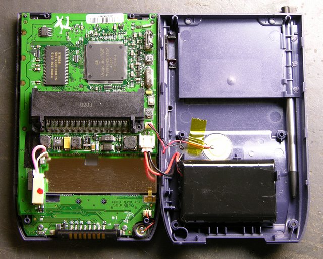
Visor Prism interior with replacement battery

Being only slightly smaller, the replacement really doesn’t have a lot of room to move, so a small bit of foam that stayed behind is plenty to hold it in place.

There’s a small ridge of blue plastic just above the upper left corner of the battery. I had to poke the wires so they went to the left of it before I could close the case, after which reassembly was quite easy.

All Data Lost (As Expected)

The original Visor and Visor Deluxe had small batteries inside to retain memory while you were replacing their AAA cells. The Prism, having an internal rechargeable battery, apparently does not have a memory retention battery. After the replacement, it came up in touchscreen calibration mode, with date and other preferences unset and all my programs and data gone.

No matter; I’ll resync at work tomorrow. It’s a good opportunity to make sure I’ve backed up my few third-party programs correctly. (I use FileZ to twiddle the backup bits on various softwares, hopefully to make my backup strategy smarter than the default, but one never knows until one tries.)

And I’m looking forward to checking the new battery life.

Update: All applications and data restored as expected.

Baldwin Organ Demolished / Free Vacuum Tubes

Friday, October 12th, 2007

The Baldwin electronic organ I was trying to help repair has been demolished. Lawrence’s family was offered and retrieved another, more recent, in full working condition; and Jake dismantled the first one. By the time I learned of it, it was literally reduced to firewood and a pile of metal chassis, which he let me pick through.

I came home with some sheet metal, some interesting resistors that I’ll photograph later, and a box of spare vacuum tubes to give away.

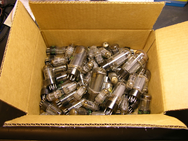
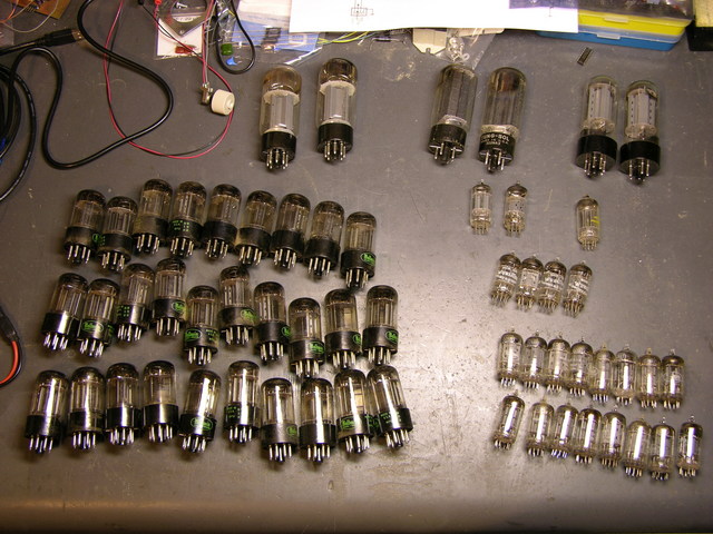
Box of vacuum tubes from Baldwin 45HP2 electronic organ

The box has been sitting in my garage waiting for me to have enough time to look through it, which I really don’t, but don’t want to put it off any longer. Here’s what’s in it:

Vacuum tubes from Baldin 45HP2 electronic organ

Crazy Keith’s Vacuum Tube Giveaway!!!

By my count, that’s:

Qty Remaining Tube
2 2 7027A
2 2 322NA3
2 2 unknown
29 29 Baldwin brand 6SN7 GTB
16 16 Bandwin brand 12AX7
4 4 Wurlitzer brand 12AX7
3 3 different, unknown brands 12AX7

I have no use for them, and I’d like to give them away to someone who does. If you have interest in them, please post a comment below indicating:

  • How many of which tubes you want
  • What you want them for
  • How I can contact you

I’ve set my blog not to auto-post your comments, so your information will be seen only by me.

I think there will be very little demand, so I expect I’ll be delighted to send them all to the first person who asks. But I’m going to be gone for two weeks; and to play fair, will evaluate all requests when I get back. If there’s more demand than I expect, I’ll lean toward charitable organizations like churches and museums, generally followed by anyone else on a first-come basis.

US shipments only, please; or you’d better have a pretty good story about how easy and hassle-free it’s going to be for me to ship out of the country.

I can’t find my tube tester, so I can’t tell you the condition of any of them. But the organ was working before it didn’t, so I suspect most of them are as good as one could expect them to be.

Or Maybe Not Giving Them Away (Or Maybe So)

13-Oct-2007

A reader advised that I should check prices on eBay, and I find that the tubes might actually bring some real money. I’m going to have to give this some thought — giving them away to a lot of different people versus putting money in Jake’s college fund. It’s not a foregone conclusion, and I’ll probably end up doing some kind of mix, so keep the requests coming.

29-Apr-2008

I haven’t got ’round to checking eBay yet; but all of the tubes are now spoken for if I do give them away, so I’m no longer accepting requests. Thank you all for your interest!

MP3 of Noise from Baldwin 45HP2 Organ

Tuesday, September 4th, 2007

Here’s an MP3 file of the noise the organ is making. It’s about 24 seconds:

  • The pop of the power switch being turned on.
  • Silence and the noise fading in as the tubes warm up.
  • Loud noise.
  • Faint notes — me playing on the keyboard. I could adjust the manual and pedal volumes to any mix I wanted; that’s just where they happened to be set.
  • Fade out after I turned off the power.

Note that the noise is continuous the whole time the organ is on — not just when playing the keyboard or pedals. And my iBook’s internal microphone didn’t capture the lower octaves of the noise at all — the sputter goes down further than I can hear playing back this sample.

Maybe this helps?

Advice Wanted: Troubleshooting a Baldwin 45HP2 Vacuum Tube Organ

Saturday, September 1st, 2007

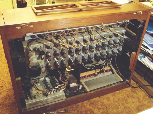
Baldwin Electronic Organ Model 45HP2, back open

My friend Lawrence’s son Jacob has just been given a Baldwin Electronic Organ, model 45HP2. It’s big and old and made with vacuum tubes and point-to-point wiring (no printed circuit boards), and it has a problem: The speaker for the pedals (that you press with your feet) continually puts out static that sounds like a low-pitched crackle. It’s definitely not 60Hz hum, nor does it sound like turntable rumble — it’s very irregular in both pitch and amplitude.

Particularly vexing is that the organ was reported to work perfectly before it was moved 60+ miles in a U-Haul-type trailer. So whatever is wrong with it probably has a mechanical origin — a damaged tube, a part or connector that needs to be reseated, or a joint that needs to be resoldered.

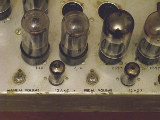
Baldwin Electronic Organ Model 45HP2, amplifier closeup

The amplifier chassis has separate volume controls for the manual (keyboard) and pedal (footboard), and turning the pedal volume all the way down eliminates the noise. So it definitely seems to be coming from the pedal section — either a tone generator or the amplifier.

The problem would be easy to repair if it were a simple matter of replacing a bad vacuum tube, so we’ve started investigating in that direction. I had Jake swap the two 12AX7 tubes on the amplifier to see whether the problem followed the tube to the manual speaker, but no change. I should probably have him swap the 616s and 7027s as well.

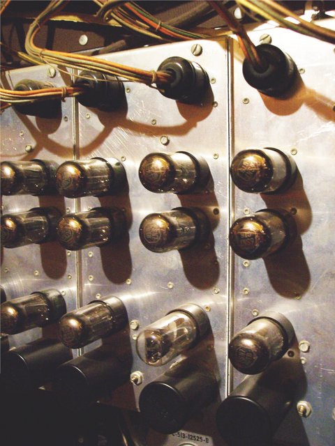
Baldwin Electronic Organ Model 45HP2, tone generator closeup

The tone generators run across the upper part of the back of the organ, with a column for each note of the scale, two columns per “board.” I believe the connector at the top brings in the “requests” for that tone in each octave — probably in analog form, as a sum of all the different sources needing that pitch (for a fundamental or harmonic frequency).

The boards are presumably the oscillators, and there’s a bus (I assume the tone output bus) made of 1/8″ rods at the bottom of the inside of the cage. My guess is that the pedal tones go onto a different rod in the bus than the manual tones; but without a schematic, with the high voltages I expect are present in a tube system, and with not much time spent so far, I haven’t tried to determine which one. It’d be fruitful to disconnect the pedal tone generator output from the amplifier, to isolate the problem to the oscillator or amplifier section, if we knew which it was.

All of the oscillator tubes are identical (6SN7 GTB), and I did have Jake rotate them within all the oscillators (top two down one, bottom to top), thinking that if an oscillator tube were the problem, the nature of the noise might change if the tube were in a different position. No change so far.

If there’s anyone out there with experience with this type of thing, I’d be very grateful for any advice you want to throw my way.