Archive for the ‘Circuits’ Category

Reducing Kickback Noise in Soundcraft Spirit E6 Mixer Switching Power Supply

Sunday, April 26th, 2009

Last weekend, I had repaired a Soundcraft mixer switching power supply, but still had switching noise spikes from the transformer primary showing up on the circuit’s ground, and asked whether anyone could suggest how to reduce them or whether they were an artifact of the way I was using the oscilloscope.

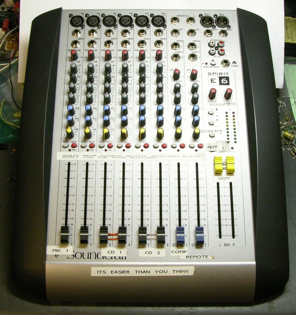
Soundcraft Spirit E6 Audio Mixer

Many thanks to everyone who wrote in with ideas! Because of your suggestions, the mixer is now fixed (enough), back together, and ready to go back to the radio lab.

Here were the ideas and their results:

(more…)

Repairing a Soundcraft Spirit E6 Mixer Switching Power Supply

Sunday, April 19th, 2009

A few weeks ago, John mentioned to me that one of the audio mixers in the art and technology / Internet radio station lab had stopped powering on. I said I’d have a look at the power supply and see if I could fix it, and he sent it with me. Turns out we both got a little more than we bargained for — I in terms of effort required and he in terms of time without the mixer.

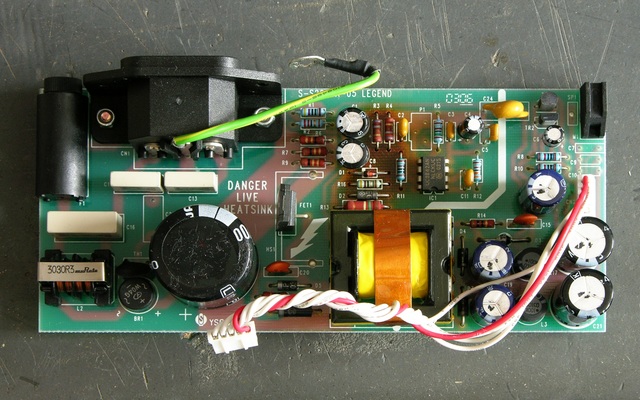
Soundcraft Spirit E6 mixer power supply board

I didn’t know whether it’d be a linear or switching power supply, and it turned out to be switching. I figured it’d just have some baked electrolytic capacitors I could replace, and it turned out that was just the beginning.

I’ve got it mostly fixed now, and it’s been a long and interesting road.

(more…)

Speaker to Preamp Adapter for Jeremy

Friday, February 6th, 2009

Jeremy and I have been kicking around ideas we’d like to see in a 1U rackmount audio mixer. I’d like to be able to mix my synths and digital piano together with another audio source so I can play along with a CD to figure out the keyboard part, without having to have separate speakers for the keyboards as I do now. Jeremy would like to be able to listen to his own selection of background music while he’s playing (some) video games at his entertainment system and projector. I’d like to be able to record my synth output into my iBook without having to disconnect and recable everything — and without necessarily recording audio from the CD I might be playing along to.

Once we figure out the number and types of inputs and outputs we want, we’ll go shopping and see if such a mixer already exists at a price commensurate with our needs. If so, buy. If not, talk about building.

Meanwhile, we got distracted by Jeremy’s receiver. Some of his audio sources are digital, so we thought we’d need his receiver to decode them before going to an analog mixer. And his receiver doesn’t have an effects loop or tape monitor, so we’d need to use line or preamp outputs and an outboard amplifier for at least his main speakers. And he doesn’t have preamp outs, so I started talking about tapping his speaker outputs and at about that point this degenerated into a game of “okay can we just get his receiver to feed through one of my SAE A502 amps and power his speakers.”

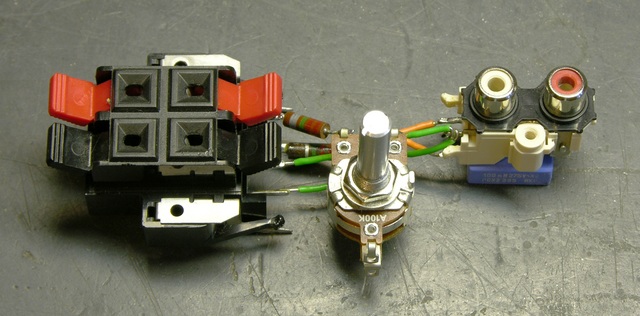
Speaker to preamp adapter, top

The answer, of course, is yes.

And by the way, all of his digital audio sources have analog outputs right next to them that we can use for our analog mix, so all of this was completely pointless. :-)

(more…)

LM34DZ Fahrenheit Temperature Sensor

Monday, February 2nd, 2009

This started as notes I made to myself long ago for the LogoChip, but they apply equally to the Arduino A/D converters.

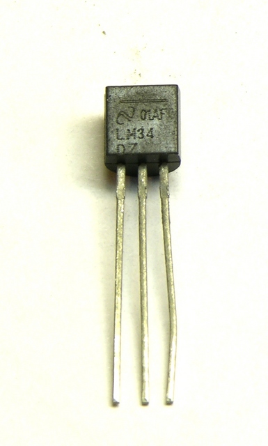
The LM34DZ is a temperature sensor in a TO-92 case available from All Electronics for $2.50. It has the handy characteristic of reading an output voltage that directly corresponds to Fahrenheit temperature in a ratio of 10mV per °F. That is, at 70°F it reads 70 * 10mV = 700mV.

LM34DZ Fahrenheit temperature sensor

With a direct output voltage (rather than the varying resistance that many thermal probes provide), it’s perfect for hooking to a microcontroller A/D input. So, how to convert the A/D reading back into Fahrenheit temperature?

Well, the sensor reads 10mV (or .01V) per °F. Microcontroller A/D converters tend to have 5V input and read 1024 steps over the 0-5V range.

1024 steps / 5V ≈ 205 steps / V

So

(.01V / °F) * (205 steps / V) ≈ 2 steps / °F

Thus you can get a “maybe close enough” approximation with code like

tempF = analogRead(lm34Pin) / 2;

With a conversion error of +2.4%, this’ll get you within a couple of degrees at room temperature — close enough to make some macro-level observations about whether it’s getting warmer or colder for a physical computing project. Since the stated accuracy is only 1°F anyway, that’s not too bad.

If you need a more accurate conversion, you’ll need to use floating-point arithmetic if you have it (which the Arduino doesn’t [correction: does]) or find a fixed-point arithmetic library if you don’t. Or if your integer variables are large enough (at least 17 unsigned bits for temperatures up to 127°F, 18 bits up to 255°F), you can rearrange the order of calculation like so:

tempF = (1024 * analogRead(lm34Pin)) / 5;

Edge-Lit Plexiglas Demo

Thursday, November 6th, 2008

11-Nov-2008

Welcome, Make and Gizmodo readers! I didn’t expect this kind of attention; but you mention light sabers, I guess geeks like us are bound to get excited. :-)

This was meant to be a crude, quick proof-of-concept prototype, and at that it succeeded. I now have 500 white SMT LEDs on the way from Hong Kong; and when they arrive, they’ll each — grain of rice sized — get glued to the end of a piece of plexi, where they’ll be nearly invisible when off. It’s up to Lisa whether the connecting wires will be visible or minimal; and bless her heart, she says she wants to incorporate visible wires into this piece, so I don’t have to mess with 1000 hair-thin, enamel-coated wires.

Finally, this is only good for artistic purposes or accent lighting. As you may have noticed when shopping for LED light-bulb replacements, there’s very little out there even close to the brightness of incandescents. If you want to light a hallway as you walk through, I’d suggest Piranha (bright) or Luxeon (brighter) LEDs in the baseboards and an ultrasonic rangefinder at the end of the hallway to determine your position.


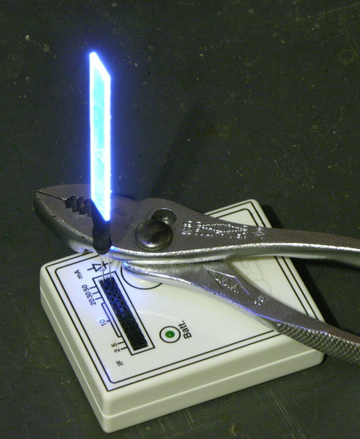
Edge-lit plexiglas strip in LED tester

I have the privilege of working with Lisa Rundstrom on an art installation for a show at the end of November. Lisa does amazing work with plastic (especially acrylic) and light (really, go look at her site), and we’re planning a cloud of 200+ hanging acrylic pieces, edge-lit with white LEDs, interacting with audience members.

If I don’t descend into gibbering madness from the impending deadline, the piece is going to be amazing. (If I do descend into gibbering madness, I expect that’ll be amazing too.)

Our art / technology / education collective has been meeting once a week in preparation for the show, and last night I built a little demo to give a rough idea of what controlled LEDs could look like.

(more…)

Arduino MIDI Volume Pedal

Saturday, July 12th, 2008

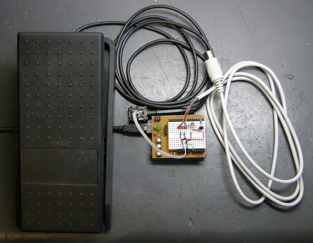
I’m playing keyboards this fall in another rock concert to benefit the high school robotics team, and for some of the tunes I need to be able to fade an organ in and out over a period of a measure or two. My keyboards are velocity-sensitive, so if you hit the keys harder they play louder (like a piano); and they have aftertouch, so if you press down extra-hard on the keys you can get special effects. But there’s no good way to change the volume of their organ sounds dynamically, and these synths don’t have inputs for volume pedals.

This is the MIDI volume pedal project I was starting to work on when I took apart a Baldwin organ swell pedal and decided to leave it intact based on what I found inside. I got another analog volume pedal from a pile of unknown origin at the school lab and finished the job.

Homebrew MIDI volume pedal using Arduino

(more…)

SOIC Breakout Boards

Monday, May 26th, 2008

I’m getting ready to collaborate with Cort on a project using ICs that aren’t available as DIPs; so I got some SOIC samples, and this weekend I hacked up some carrier boards to break them out to .6″-spacing DIP.

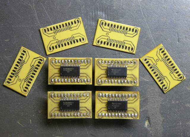
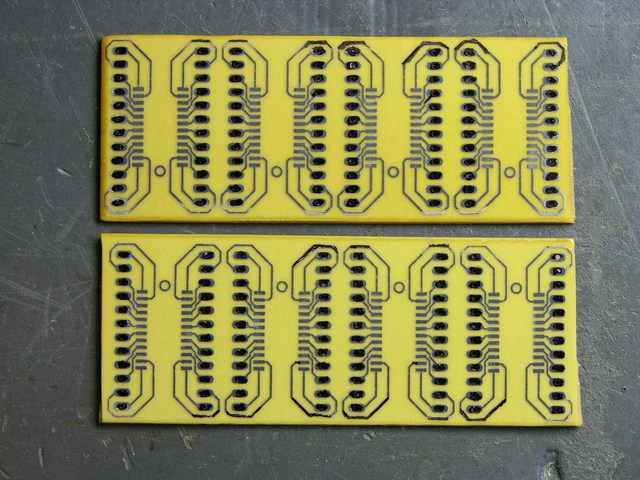
Completed SOIC-24 breakout boards

I made a few extras — as many as I could fit in my little etching tray — so I’ll be set for a while.

I also want to give the design away to anyone who wants it. It’s nothing special, but it might save someone else some time. So I’ve created a Free Circuits page where I’ll post things for free download under a Creative Commons License Creative Commons Attribution-Share Alike 3.0 Unported License. All the code I post here I do with the intent that it may be useful to someone else; but it’s nice to be explicit about it once in a while.

On to the Board . . .

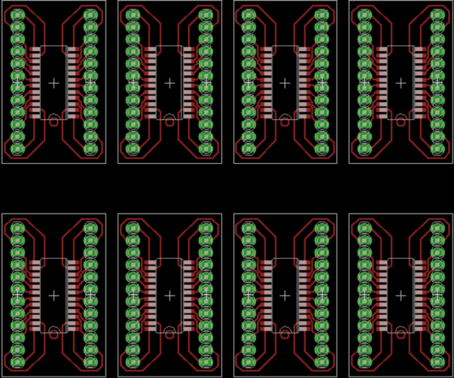
I laid out the board, then panelized it as large as I could fit within free EAGLE, which turned out to be four wide by two high.

Circuit board layout of SOIC-24 breakout board, panelized 4x2

Here I’ve corrected it to put space between adjacent boards; but I didn’t think of that until after I’d etched mine, which made for some tricky separating.

SOIC-24 breakout boards, etched

I did my usual toner transfer with the household iron, then used a Staedtler super-fine pen to touch up some spotty areas along the edges. The boards came out really well, in spite of using fairly tight spacing (12-mil traces with 9-mil separation by the middle pins). I inspected all the traces with a photographer’s loupe to be sure they had continuity where they should and separation where they shouldn’t.

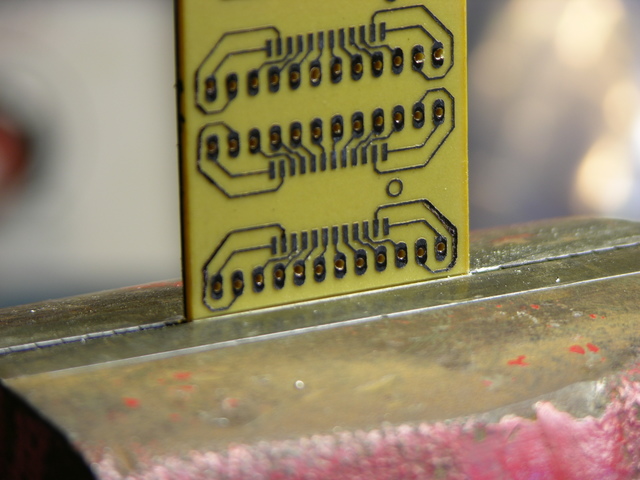
PCB scored in vise

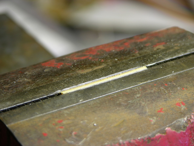
Having stupidly left the individual boards touching each other on the layout, I wasn’t quite sure how I was going to get them apart cleanly. But I tried a new method, clamping them in my bench vise and using the jaw’s smooth edge as a guide to score front and back with the corner of my best $3 chisel. You can just barely see the score line above.

PCB scored and snapped cleanly in vise

The boards snapped off clean as could be! I’ll definitely be using this method more in the future, even on boards I haven’t screwed up.

LED Calculator Prototyped with LCD

Friday, February 8th, 2008

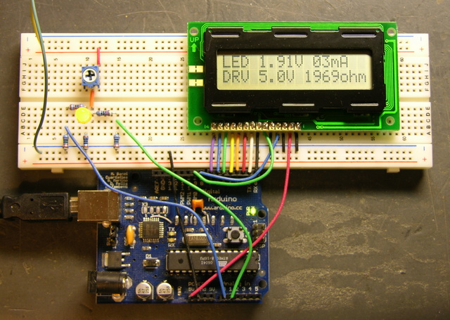
I still want to find a small LCD module for the LED calculator, so I can fit the whole thing into a box with a footprint about the size of a deck of cards. But for prototyping, I have a stack of 2×16 LCD modules about 3 1/2″ wide (viewable about 2 1/2″) from Slim, and Wednesday night I got one hooked up and working.

They’re Optrex DMC-16207 modules, and they seem to be using the Hitachi chipset that everyone uses, or at least an equivalent, although I didn’t know that at the time. Searching online, I had a hard time finding data on this exact module, but came across a mechanical drawing, a module user’s manual, and finally a full datasheet.

Interfacing the Arduino and LCD

I dived in and wrote my own LCD interfacing code. I found out in retrospect that there are several other Arduino LCD interfacing projects out there:

But all of them are using hard-coded delays to pause while the LCD processes commands, rather than checking the busy flag. To be sure, I’m doing the same thing right now in my first draft of the code; but I’m going to go back and clean it up to do it right.

Also, I haven’t checked all of them, but at least one is using digitalWrite() to manipulate each bit of the port register individually. Since I’m dedicating eight Arduino lines to the LCD’s I/O port, I can write the port register as a byte rather than twiddling individual bits, saving time and effort.

My goal will be to write a nice library module/class that encompasses these different approaches (8-wire vs 4-wire, busy flag vs hard-coded delays, read/write interaction vs hardwired write-only) and presents a clean interface to the programmer to select the options. Of course, for now, I just wanted to get it up and running.

I found this ATmega to Arduino pin mapping, which confirmed that Arduino digital lines 0-7 are PORTD lines 0-7. And the Arduino port register reference shows that DDRX and PORTX are defined as Arduino variables; so writing to a port is as easy as PORTD = $ff . It’s very nice that they left those low-level features exposed, even though in most cases it’s better to use the higher-level interface for portability.

Calculator Prototype

So here’s the work in progress.

LED calculator prototype with LCD on breadboard

The Arduino is getting power from USB and supplying 5V power to the LCD. The LCD contrast is hard-wired to ground. Although it actually looks pretty good right now, I’ll want to put in a potentiometer to adjust contrast. And I’m still using my bench power supply to run the LED circuit at 9V.

I don’t have a method built to select the voltage of the target circuit — the software is assuming 5V for now. The easy thing to do would be pushbuttons to bump the desired voltage up and down. It’d be kind of fun to do it with a spinny-wheel, although I’m not sure how much that would increase the cost, and I’m concerned about overengineering this thing if I really want to offer it as a kit. Maybe another potentiometer is a good compromise.

However the target voltage is selected, I need to determine the selectable range (which could of course be overridden by an owner with an AVR programmer). I’m thinking 3 – 15V in .1V increments. Is that enough?

LED Calculator Breadboarded

Saturday, February 2nd, 2008

After receiving some encouragement, I went ahead and breadboarded the measurement circuit for the LED calculator. Someone may suggest a better way to do it, but here’s what I’ve been carrying around in my head:

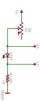
LED calculator drive circuit

R2, a 1KΩ potentiometer used as a variable resistor, controls the LED brightness. R1, a precision 100Ω resistor, limits the maximum LED current and acts as a sense resistor.

By measuring V1, we can calculate I1 = V1 / 100Ω. Since ILED = I1, we’ve determined the LED current. And VLED = V2 – V1, so we can determine the LED voltage drop as well.

The value of R2 isn’t critical. With a supply voltage of 9V and a very low LED drop of 1V, a 1KΩ variable resistor allows us to test LED currents down to (9V – 1V) / (1KΩ + 100Ω) ≈ 7mA, which is probably low enough for most applications. To be able to test lower, increase the range of R2.

Test Measurements

I built this much of the circuit and took measurements of a few different LEDs at a few different brightnesses, to make sure the potentiometer would really work the way I expected, and that I hadn’t made any stupid mistakes in the voltage calculations.

Color V1 V2 VLED ILED
green .71V 2.70V 1.99V 7mA
2.00V 4.04V 2.04V 20mA
3.45V 5.55V 2.10V 35mA
red .73V 2.55V 1.82V 7mA
2.00V 3.88V 1.88V 20mA
7.28V 9.24V 1.96V 73mA
blue .61V 3.61V 3.00V 6mA
1.12V 4.23V 3.11V 11mA
2.00V 5.27V 3.27V 20mA
5.56V 9.24V 3.68V 56mA

The measurements make sense — each LED’s forward voltage drop increases slightly as the current increases. If I remember my semiconductor theory correctly, that’s called the ohmic region of operation, in which a diode behaves like a very low-valued resistor.

Automating the Measurement

In a self-contained LED calculator, the voltages will need to be read by a microcontroller, which will also drive an LCD. For now, I used my Arduino and had it send results to the host computer.

Depending on the position of potentiometer R2, V2 can range up to the supply voltage of 9V (or whatever); and V1 can range up to the LED’s forward voltage drop less than that. I’m pretty sure the microcontroller’s A/D converters don’t like inputs over 5V, so I needed to divide V1 and V2 to lower their ranges before feeding them into the ADCs. I used two pair of precision 10KΩ resistors for that.

LED calculator measurement circuit

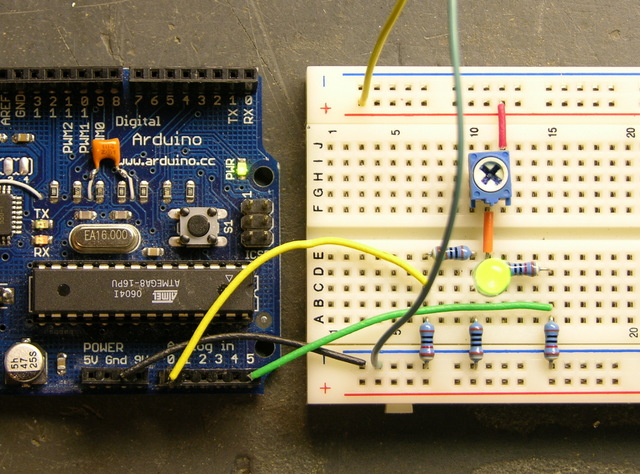
All put together on the breadboard, it looks like this.

LED calculator circuit, breadboarded

And with a little Arduino program running to read the inputs, scale from 1024 steps back up to a range of 5V and then double to compensate for the voltage division, and calculate all the values, I get this.

Output from LED calculator Arduino prototype

Putting It in a Box

I’ll probably program an Atmel chip directly, because I don’t need all the USB baggage. Even a Boarduino has prototyping parts on it that I don’t need here.

I need to think carefully about the LCD screen, to have enough room to display all the information and still be small enough to fit into a reasonable project box. A cell phone screen would be the perfect form factor, but really drives up the cost and complexity. I think about a 4×16 character display would be okay; 4×10 would be tight for the text and I’m afraid 4×20 would be too wide for the box.

LED 2.10V 35mA
DRV 8.4V 180ohm

Okay, 2×15 is a bare minimum. All Electronics has a 2×16 module that’s 4″ wide and another that’s 3.15″ wide, which suggests having to build the calculator in landscape mode. Not wild about that. Digi-Key has 4×16 starting at $27 and — hey! — a comparatively svelte 2.6″ wide 2×16 at $5.88.

Reverse-Engineering a Flammable Gas Detector

Sunday, November 4th, 2007

My boss’s in-laws have some property in the country where they like to camp out on weekends, and they have a trailer parked there with propane heat for cold evenings. This summer or fall, my boss asked me whether I knew of a gas leak detector; his dad-in-law thinks the tank or plumbing is leaking, and they’d like to fix the leak before using it much this winter.

I said that I didn’t know where to buy one and he could Google for them as easily as I could; but (only half tongue-in-cheek) that I could build him one. He said he needed it by this winter (harrumph!) and went on his way.

I actually had an ace up my sleeve: I already have a box of flammable gas detectors.
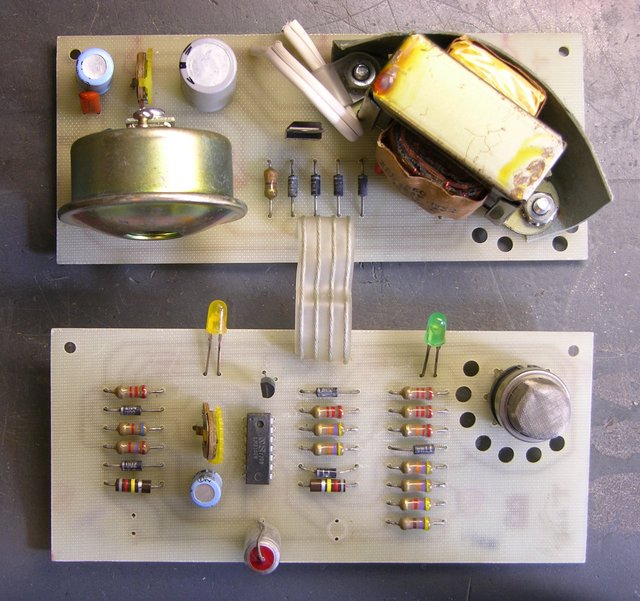
Flammable gas detector, top view

I picked up several of these at Lloyd’s electronics about eighteen years ago, I think for $1 each, in one of their dump bins. At the time, I was probably after the buzzers more than anything else. But I remember that I had hooked one up long enough to test it, and it worked. Trim the sensitivity and blow flammable gas into the element, and the buzzer goes off. (Flammable gas . . . mechanical buzzer . . . never mind . . .)

Now, I could loan him one of these, but they require 110VAC, they’re not safely packaged for mobile use, and they only give a binary output. So I figured I could reuse the sensor element from one and construct a tricorder handheld unit with analog (or at least more than binary) readout.

I didn’t make any promises and haven’t mentioned that I’m pursuing this, so there’s no pressure. But once it occurred to me, it seemed like an interesting project; so here I go.

Drawing the Whole Schematic

Why draw out the whole schematic? Because I had no idea how the sensor element worked. I wasn’t rapt to know how some unknown manufacturer had designed an alarm circuit; I simply needed to know how to work the sensor. With no part number on it and no knowledge of the field of gas detection, the easiest method seemed to be to see what the original circuit did and make guesses about the sensor from there.

In retrospect, everything I need to know about the sensor I could have figured out with my multimeter instead of figuring out the circuit rather than after figuring it out. But no harm done.

Scanning and Drawing

I started by scanning the solder side of both boards into the GIMP and mirroring them to give me a top-side view. The power board is pretty simple, so I ran an edge-detection to emphasize the traces against the light-colored board, printed it, then highlighted the traces and hand-drew the components.
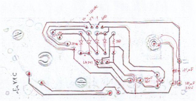
Flammable gas detector, power board scan / schematic

It has a bridge rectifier with a floating LM341 that’s presently delivering ~15VDC, the buzzer, and 1.25VAC from a separate transformer secondary that gets added to DC V+ and sent on one pin to the sensor board.

For the main sensor board, I set the scan at 1:1 scale in the GIMP and dragged rules over it so I could quickly identify the coordinates of each pin. (I didn’t draw them as lines, so they don’t show in this export.)
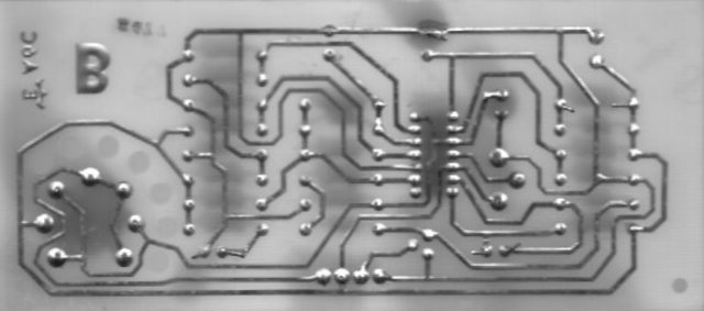
Flammable gas detector, solder-side scan

I then created an EAGLE schematic / board layout, adding and placing each component and then each trace, until my EAGLE copy matched the scan (more or less).
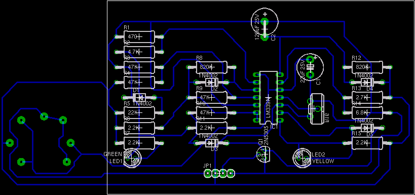
Flammable gas detector board layout

I first placed the parts on the schematic in the same place as on the board, to help keep track of what I was doing, so the schematic looked really ugly:
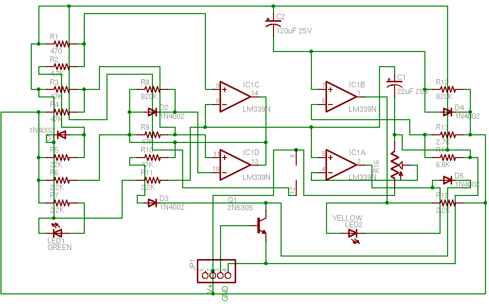
Flammable gas detector schematic in board placement

And then it was just a matter of dragging the schematic around into a more logical configuration.
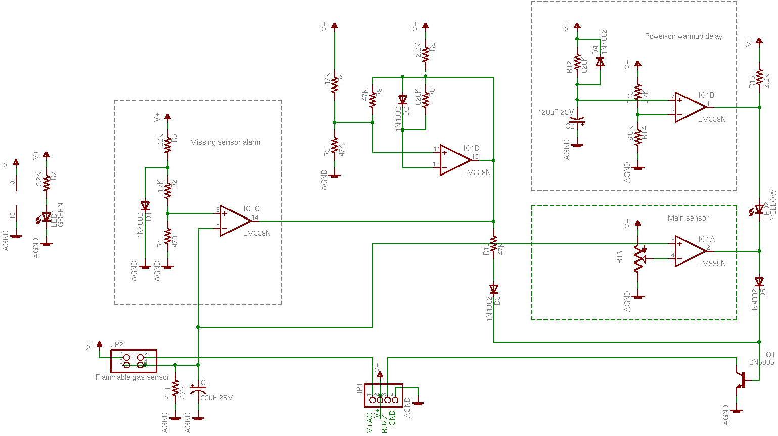
Flammable gas detector schematic diagram

The image compresses badly, so you’ll need to open that into a separate window if you’re interested in following along.

How It Works

In high-level terms, the sensor element (lower left) puts out some kind of voltage that runs through a bunch of comparators, and switches an NPN transistor that grounds the buzzer. Detect gas, make noise. But it took me a while to figure out why so darn many comparator stages are used.

First, it’s worth remembering what the LM339 comparator does. It has open-collector outputs, so you can tie its outputs together in a wire-AND (or active-low OR) configuration. If any output is low, the line goes low; if all outputs are high(-impedance), the pull-up resistor pulls the line high.

This configuration is used twice in the circuit: In R15, IC1B, and IC1A; and in R6, IC1D, and IC1C. IC1A and IC1B can each pull down R15 and keep its high signal from getting through to Q1; likewise IC1C and IC1D can each pull down R6 and keep its high signal from getting through. Diodes D3 and D5 perform diode OR logic: either one permits a high signal through to Q1, but a low signal is blocked and can’t pull down the other’s high signal.

So Q1 will have its base pulled high and activate the buzzer when

(IC1A AND IC1B) OR (IC1C AND IC1D)

Comparators

Now we just need to know what each comparator is doing.
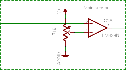
Flammable gas detector schematic diagram, gate IC1A

IC1A is simple: The sensor’s voltage is compared to an adjustable reference. This is the main action of the whole device.
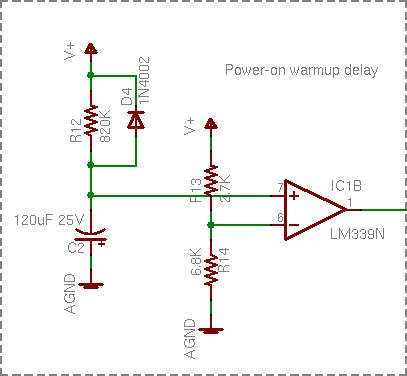
Flammable gas detector schematic diagram, gate IC1B

IC1B was the next one I figured out, although I didn’t have it quite right at first. Capacitor C2 charges through R12 and IC1B compares its voltage to a reference, so it’s a power-on delay. I wasn’t paying attention to how high R12′s resistance is (820kΩ), though, and I figured IC1B’s purpose was to keep the alarm from blatting when the power first comes on and before it stabilizes. That’s not quite it, which I’ll explain in a bit.

Before I move on, note the entire signal chain of V+, R15, IC1B, LED2, IC1A, D5, and Q1 along the right edge of the full schematic. IC1B and IC1A can each ground R15 and prevent it from pulling up Q1′s base.

IC1B also controls LED2, though. LED2′s cathode is grounded through either IC1A or Q1, so IC1A has no impact on LED2; but IC1B can pull down LED2′s anode. In English, LED2 indicates that the circuit is warmed up and ready to operate.

I find this extremely elegant. It’s not complicated; but in today’s world of cheap microcontrollers and FPGAs, I think clever thought has too often lost way to throwing lots of gates at a problem.

Continuing:
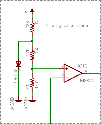
Flammable gas detector schematic diagram, gate IC1C

IC1C’s voltage divider seemed a bit odd, but it’s just establishing a very low reference. D1′s forward voltage is about .5V, and R2 – R1 divide that down to .05V. If this reference is higher than the sensor voltage, then trigger the alarm. Ahhh, it’s a missing sensor detector. The sensor is pluggable; if it got knocked loose, or broken, or maliciously removed, the alarm sounds a warning. Very nice.

IC1D I still don’t get. Best I’m able to measure it in circuit, it appears to be oscillating around 1.3MHz at startup until IC1C pulls it low and shuts it down. I have no idea what it’s supposed to be doing. And yes, I’m fairly sure I drew its schematic right.

Comparator Recap

So if the sensor element is missing (IC1C), the alarm sounds. Otherwise, once the circuit is warmed up (IC1B), a high enough voltage from the sensor (IC1A) sounds the alarm. Simple!

And it still doesn’t tell me how the sensor works. Feh.

The Sensor
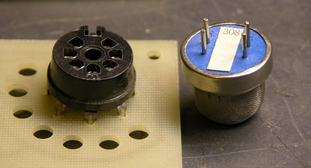
Flammable gas sensor and socket

It’s not obvious from the aerial photograph of the whole board that the sensor has four pins in a rectangle, and that the socket has seven pins and the sensor can fit it in two different rotations. From the solder-side picture, though, the socket is wired such that (assuming the sensor is electrically symmetric) the sensor will be connected the same either way. So assume that the sensor is symmetric electrically as well as physically — that is, the pairs of pins are functionally interchangeable.

Looking back at the board layout and tracing carefully, V+ and V+AC connect across one long side of the sensor’s pinout rectangle. The other long side is wired directly together and functions as the output, connecting to R11 and C1 (both grounded) on the way. So: The sensor normally has a high resistance between its power pins and output pins; that resistance lowers when flammable gas is nearby, changing the sensor – R11 voltage divider and raising the voltage.

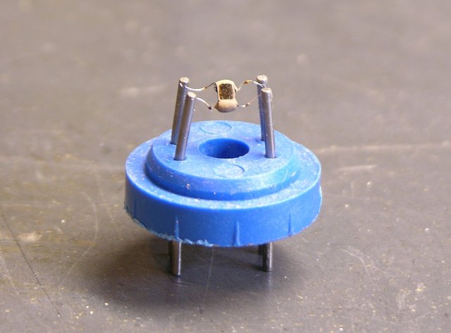
But why supply 15VDC + 1.25VAC to the power pins? I didn’t understand, so I cleaned the power supply board, insulated its 110V traces with electrical tape, plugged the circuit in, and took some measurements — and still didn’t get it. So I looked through my box for the sensor with the most-crushed windscreen and peeled it apart.
Flammable gas detector sensor

And I searched for flammable gas sensors online, eventually finding this slide on catalytic sensors from an OSHA workshop titled What to Look for in Gas Detection and Measurement Instrumentation.

It doesn’t match exactly, but the basic idea seems to be that you heat up a specially-coated thermistor bead; flammable gas oxidizes on it, heating it further; and you measure the change in resistance due to the increase in heat.

And things start to make more sense. You heat the bead with a small amount of AC across pins 1 and 2, and you run that AC on a DC offset so you can more easily measure resistance changes between pins 1-2 and 3-4 by making it part of a much higher voltage DC voltage divider. I can deal with this.

Sensor Measurements

Running the open sensor in the live circuit shows that its bead heats up to about 160°F — and it takes about half a minute to warm up, hence the long delay from R12 – C2 – IC1B before turning on the yellow “ready” LED. (Not just a power-up delay, but a warmup delay.) The sensor also responds a lot more rapidly to approaching and dispersing gas with the windscreen removed.

The sensor output voltage across C1 is 0V when the circuit is first powered up, rises to about 4V when the element is warm, and climbs as close as I care to measure to V+ (15V) when gas is present. The sensor and R12 (2.2KΩ) form a voltage divider across the 15V supply, so:

Condition VC1 Rsensor
cold 0V
warm 4V ~600Ω
gas present 15V << 2.2KΩ

Finally, I measure each “long leg” of the sensor at 2Ω and I measure about half an amp flowing on the “heater” side. And that’s all I need to know about the sensor.

Building a Handheld

That’s next. I’m not keen to build a biased AC supply into a handheld unit, but nor do I need to. I can heat the element with a high-frequency square wave; that simply means that the sensor output will also be a square wave, and I can deal with that by integrating the output or using a peak level detector (essentially the same thing).

It takes about half a watt to heat the bead to 160°F, and that’ll drain a 9V battery fairly quickly with constant use, but I use rechargeables anyway. And I may find I don’t have to heat it quite that much.

Where am I going to find a reasonable socket for the darn thing? I’d really prefer a nice rectangular configuration, instead of perpetuating the weird any-rotation-you-want of the original.