Introduction to the LogoChip
A lot of the work in the Technology: Art and Sound by Design class will revolve around the LogoChip, a PIC18F2320 microcontroller (~$8 in 28-pin DIP) with scads of I/O pins and a Logo byte-code interpreter. (The Logo code is compiled on a host computer and downloaded to the chip.) The getting started guide gives examples to flash LEDs, beep piezo speakers, and move Lego motors.
The chip looks very promising for my own hobby use as well. I’ve been intending to dive into microcontrollers for a long time, and always assumed it’d be PICs. I have a BASIC Stamp (and a separate PIC) on my SumoBot, so that’d be one entry into microcontroller programming; but the LogoChip appears to be even easier to get into.
I’d been planning to follow up to my tilt sensor project with a PROM-based controller, but a little logic tells me that I’d need to quantize the sensor’s PWM output into at least 32 slices to get acceptable motor behavior, and that’s a lot of work to do in discrete logic. I’m afraid I’d overload my small motor just with the weight of the TTL DIPs required to do that. I had really wanted to build a motor controller without a microcontroller, just to show myself that it could be done, but I think it’s time to move on.
Building Circuits
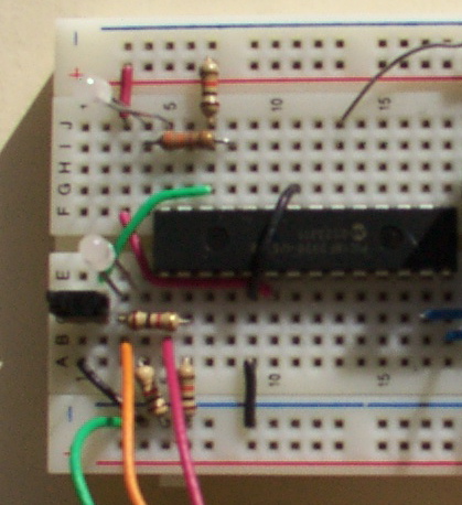
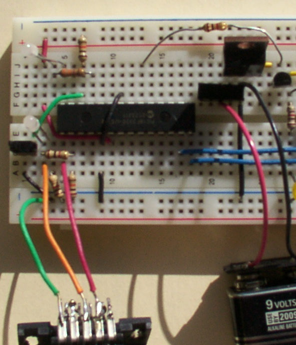
The last two nights, I’ve breadboarded the LogoChip circuit, got it communicating with a host computer, and successfully built the cloning circuit to program the LogoChip code into the blank PICs I bought. The road to success was paved with annoying obstacles, though.
The getting started guide gives a schematic and step-by-step instructions to lay out the supporting circuitry on a breadboard. Of course, I’m stingy with space (I want as much room left over for other components to experiment with), so I managed to collapse the circuitry into the smallest possible amount of space. I saved .4″ over their design! Woo-hoo!

But I built and tested it using my bench power supply, forgetting that I was planning to power it with a 9V battery and 7805 voltage regulator. After I had it all working, I didn’t have room to add the 7805, so I had to stick it down at the other end, move the power switch, etc. ERROR.

Also, the guide’s schematic for the serial interface disagrees with its visual layout instructions, and the schematic is incorrect. The indicator LED and its current-limiting resistor need to attach directly to DB-9 pin 3 (the host’s TD / chip’s RD), not to the chip’s C5 (pin 15) as shown in the schematic. When attached to C5, it appears to pull down the signal too hard, and I couldn’t get serial communications to work.
[INSERT CORRECTED SERIAL INTERFACE SCHEMATIC HERE]
And, OBTW, the LogoChip goes into the circuit UPSIDE DOWN. That’s right, engineers–don’t try to insert it with pin 1 in the usual position, ’cause that’s not the orientation they chose to use. (???!!!)
I only did that once.
Mac Interface Troubles
The guide points to the files needed to install the LogoChip Desktop Software, but doesn’t give much information about what to do with them. I’ve written more detailed instructions on the class wiki. Strangely, the Java serial communications driver seems to require Classis (OS 9) support in order to install correctly–that’s the only difference I can find between my work desktop computer (where it installed and ran fine) and my notebook computer (where it didn’t). I still plan to get this working on my notebook somehow, so watch the wiki for updates.
Cloning LogoChips
The LogoChip has a cloning process to copy the Logo firmware onto another PIC. Because you can use this to get the firmware onto a chip without a PIC programmer (which I don’t have and haven’t built yet), I ordered blank chips from Digi-Key rather than preprogrammed LogoChips from Wellesley, and John loaned me one of his chips to clone.
The clone routine is a program that has to be downloaded to the LogoChip, not a permanent part of the firmware, so I couldn’t clone until I had the serial communications working. John loaned me the chip Tuesday and I promised to have it back today (Thursday), so that put some pressure on me to get the serial issues debugged. I ended up using my wife’s Windows machine last night for the programming.
Since I’m powering my circuit from a 9V battery instead of the 4xAA 6V pack recommended by the guide, I was curious whether I’d have to add another battery for clone circuit’s programming voltage, or whether I could get away with 9V. Googling for PIC18F2320 programming voltage led me to Microchip’s programming specification, which has an AC/DC Characteristics chart waaaay at the bottom which gives a range of 9.00-13.25V for high-voltage programming. Shiny!
I grabbed the unregulated 9V straight from the battery, threw another PIC on the board, hooked it up, and downloaded the cloner code into John’s chip. (Uh, John, did you realize I’d be overwriting whatever program you already had in there? Sorry about that . . .) Pressed the Go button, and– . . . uh, the button popped right out of the breadboard. I’m gonna have to solder longer leads onto that puppy. Jammed it back in long enough to hit it, and voila! Run light went green (“doing something”) and programming light came on.
[INSERT PHOTO OF CHIP CLONING WITH LIGHTS]
After a while (don’t know if it was four minutes like the guide said) the programming light went off and the run light went red (idle), and it was done. I pulled John’s chip out of the breadboard and put it in an anti-static bag to bring back, put my new LogoChip into the master slot, and cloned it onto another blank chip to make sure it worked. Same deal–lights came on, blah blah–and now I have two LogoChips. W00T!
I tried hooking a piezo speaker to one of the pins to make a bleebledy-bloop program like the guide’s tutorial shows, but couldn’t get any sound. When I put 5V directly across it, it does click a little, so it may just need more current than the chip is supplying. I may try setting it up with a drive transistor to see if that helps; but I salvaged it out of a microwave, so I don’t actually even know for sure that it’s a speaker. Maybe it’s a secret Klingon nucrification death device.
I busted loose a piezo beeper from my stash of dead pagers, but it had SMT solder leads that I couldn’t just jam into the breadboard, so I let it go and called it a night.
And in Conclusion . . .
LogoChips are cool.