A Theremin is an electronic instrument played by waving your hands in the air near a couple of antennae. It has matched pairs of high-frequency oscillators, and the change in capacitance due to the proximity of your hand changes the frequency one oscillator in the pair, causing “beats” (heterodyning) between the pair that form audible wavelengths. The Theremin was invented early in the 20th century by Leon Theremin, a Russian physicist. It’s the spooky sound you hear in the Beach Boy’s “Good Vibrations”–although that was actually recorded with an electro-theremin, a different instrument designed to mimic the Theremin’s sound.
I don’t know when I first became aware of Theremins, but I know I’ve wanted one at least since February of 1996, when Electronics Now published “Build this Theremin,” by John Simonton of PAiA Corporation. The full PCB layout and parts were published in the magazine, and PAiA has also sold their “Theremax” kit continuously since then.
And I finally ordered one.
Two, actually; my friend Cort wants one as well.
They arrived about a week later.
Board Assembly
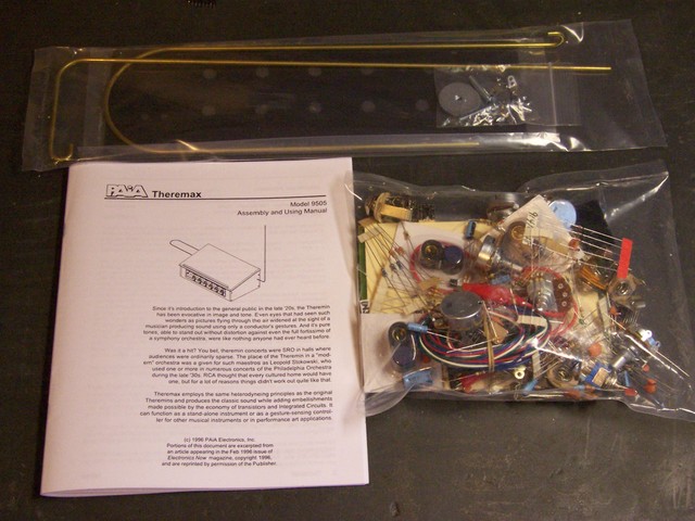
I bought the kit with the PCB and all components, and the separate partial case kit with the antennae and a nicely screened front panel. The full case kit was another $60, and I figured I could make a case that I’d be happy with for less than that. I think it says a lot about PAiA and their understanding of the hobbyist marketplace that they offer so many options, instead of forcing everyone into the same cookie cutter package.
The first thing I did was sort out all of the components. There are dozens of resistors and capacitors, a handful of transistors, four tunable inductors for the oscillators, pots and jacks for the panel (included in the parts kit, even if you don’t buy the panel), and miscellaneous bits like LEDs and ICs. They even threw in hookup wire to connect the PCB to the control panel, and a gator jumper for bypassing the volume control during one stage of hookup–literally every part you need to get up and going, except solder.
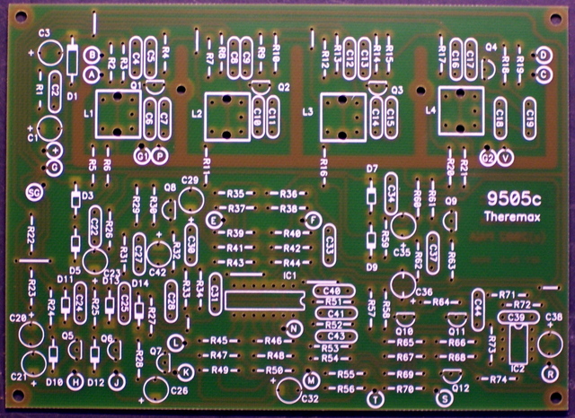
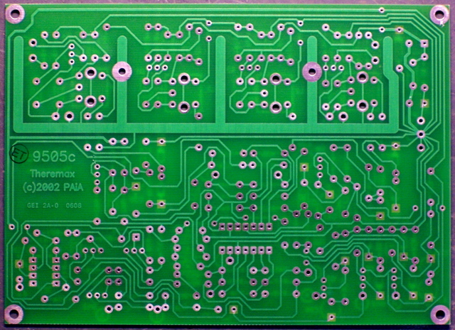
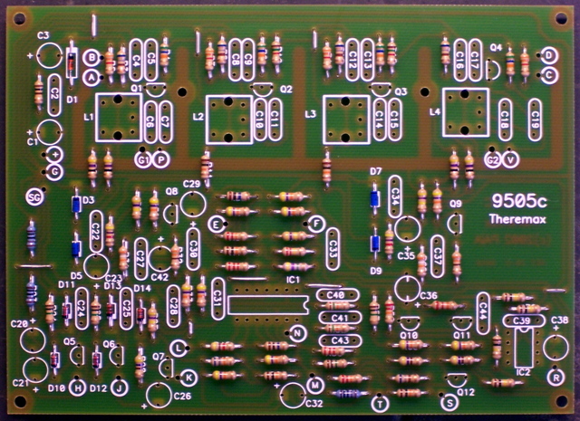
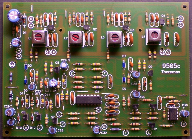
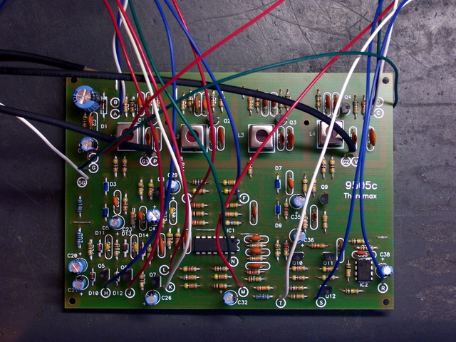
Next, I took a look at the PCB. It’s a nicely-made single-sided board, with silk-screening on the top side for component identification only. I have only two small complaints:
- The identifying marks for resistors and capacitors are under the component, so they’re no longer visible once the component is installed. I know there’s not a lot of extra room on the board for labels outside of the component footprint, but having to refer to a separate parts placement diagram really makes troubleshooting more difficult.
- The resistors and capacitors are roughly numbered from upper left to lower right; but some of the numbers stray across the board, making it hard to locate the correct part. Maybe I’m too picky, but I really like an orderly numbering system during the assembly and troubleshooting stages.
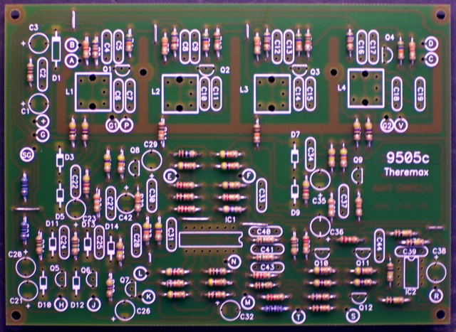
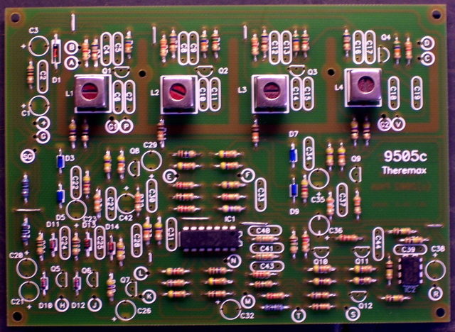
The assembly instructions give a reasonable order for soldering in the components, which I mostly followed–jumper wires and resistors first,
then diodes. Note the blue diodes near the center of the board–germanium, with a lower voltage drop for increased sensitivity. I’ve read a nice description of how that aids the Theremin circuit, although I don’t recall it at the moment.
Here I deviated slightly from the instructions’ assembly order, and installed the ICs and inductors next. Because I don’t have a cool PCB holder, I solder with the board upside down on my workbench; and because of that, I prefer to install the shortest components first and work up to the tallest,
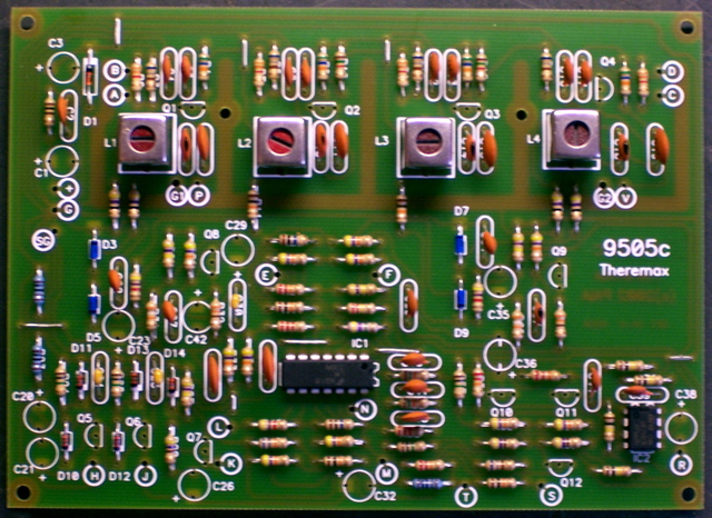
which means doing the inductors before the ceramic capacitors,
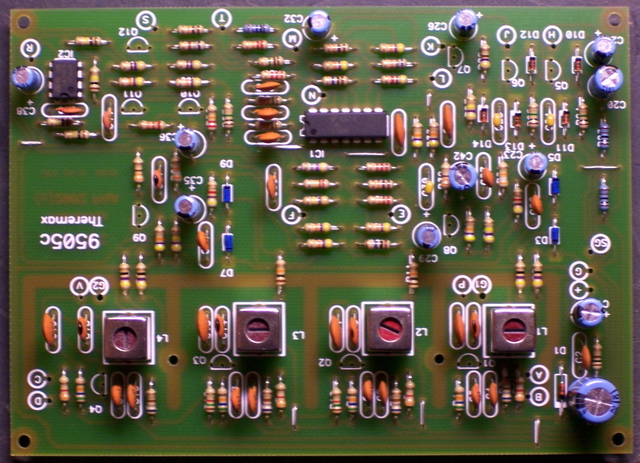
and the electrolytic capacitors last.
The transistors are actually shorter than the electrolytics, but they cling to the board pretty well, thanks to the hole spacing being considerably wider than their lead spacing.
Control Panel
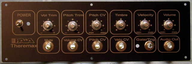
PAiA’s professionalism really shines here, and my photo doesn’t do it justice. This is a very nicely lettered control panel, as good as those on most of the equipment I own. I like the retro feel of the white paint on black brushed aluminum, rather than some glitzy decals on colored plastic that you might see these days.
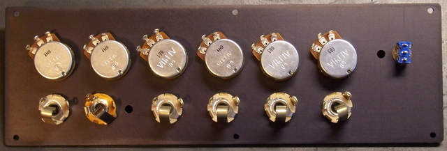
I installed all of the potentiometers and jacks, twisting them as needed to try to get the hex nuts on the front to line up evenly. (I like to use the phrase detail-oriented.)
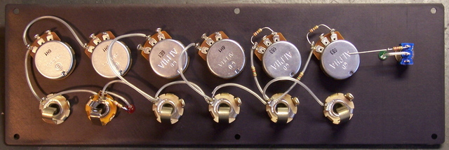
The instructions say to run bare wire from pot to pot for the ground connection; but I’m not wild about bare wire (especially when it has to loop and could be snagged and pulled out to contact something else), so I put some clear heatshrink over it for sleeving. I also built up the LED assemblies–replacing the provided dark red LEDs with my own green LED for the power light, and a matching red LED for the gate trigger indicator.
Then I soldered all the fly wires to the PCB. The assembly guide gave very specific lengths; but I think things must have shifted since that was first printed, because the wires had completely different amounts of slack once connected. I shortened some wires and should have lengthened others, and made notes about all the changes I made and further changes I should have made. Here are my notes about the colors I used and the lengths I’d recommend:
| Board | Panel | Signal | Length | Modify | Color |
|---|---|---|---|---|---|
| A | R79-2 | P trim | 9 1/2 | -1 | blue |
| B | R79-3 | P trim + | 9 1/2 | -1 | white |
| C | R80-3 | V trim + | 5 | +1 | white |
| D | R80-2 | V trim | 5 | +1 | green |
| E | R81-3 | timbre short sine | 9 1/2 | red | |
| F | R81-1 | timbre short square | 10 1/2 | -1 | blue |
| G | lug | GND | 10 1/2 | -2? | green |
| H | R82-3 | pitch CV | 12 1/2 | blue | |
| J | R83-3 | volume | 9 1/2 | red | |
| K | R84-3 | velocity | 9 1/2 | +1 | white |
| L | J3-T | velocity CV | 11 | -2 | red |
| M | J2-T | gate | 10 1/2 | -1/2 | red |
| N | J2-R | trigger | 10 1/2 | -1/2 | green |
| R | J1-T | audio out | 12 3/4 | -2 1/4 | blue |
| S | J5-T | volume CV | 16 | -6 | blue |
| T | J6-T | mute | 16 | -5 | white |
| + | S1-1 | +12V | 12 | -1 | red |
| SG | J1-S | SGND | 5 | +1 | white |
| lug | S1-3 | GND | 10 | green |
The last thing I did in that batch of soldering was run signal wires within the back of the panel. The instructions gave this step at the same time as the ground wiring, but I wanted to wait until I had the fly wires chosen so I could maintain the same color wire everywhere a signal traveled.
Next Steps
By now, I’ve connected the fly wires to the control panel, built a case, and semi-mounted the kit in the case. I’ll post those pictures soon.
