Archive for the ‘EAGLE’ Category

BatchPCB

Sunday, June 17th, 2012

My academic background is in mathematics and computer science and I’ve picked up electronics as a hobby along the way, primarily self-taught through excellent books by Forrest Mims, the easy crossovers from math and CS to digital logic and digital design (still my strongest area of electronics), a stubborn willingness to read datasheets, and a constant desire to learn.

For the last two years, I’ve been supplementing that with a formal background from my university’s EE department, taking first one and recently two classes per semester. The education is interesting and enlightening, but it does take its toll — at least forty hours a week of work, six hours of classes, and (say) twenty hours of study and homework, plus some volunteer work unrelated to those, doesn’t leave me with a lot of free time; and you can see it by the decline in my hobby activity.

I don’t want to lose sight of what I love, though; and I hope to make a small business of electronics and make a few products available for sale. So this summer I’m devoting every spare moment to get some projects off the ground. And my ally in that plan is BatchPCB.

Why Have Boards Manufactured?

In the past, I’ve done a lot of circuit prototyping on breadboards. For some types of circuits, though, the needed prototyping has more to do with physical form factor and less to do with circuit validation. (I hope to show some examples in the coming weeks.) I’ve etched my own circuit boards; I’ve imposed on friends to mill prototype boards for me; and I’ve hoped to build my own milling machine to prototype my own boards at home.

The drawback of all of these methods is the lack of plated through-holes. I’ve heard of DIY hole-plating methods, but I found them to require a prohibitive setup for chemical processing. I’ve asked everyone I know whether they can think of any source for 1.5-ish mm (60 mil) OD copper or silver tubing, thinking of making a small riveting press to flare tubing onto the PCB surface both top and bottom — and even found very small silver crimp tubes used in beadwork and jewely-making, but none as small as 1.5 mm OD, nor in a consistently appropriate length.

I’ve worked around the lack of plated through holes by laying out boards that don’t require them, always carrying a signal from top to bottom using a component lead that can be soldered on both sides. But this means no vias (soldering pins top and bottom just to change layers is a pain) and only crossing layers at resistors and diodes. It means always routing connections to electrolytic capacitors on the bottom, ’cause you can’t get to the top side of the board to solder unless you stand the capacitors way up on their leads. It means routing traces to headers only on the bottom, or sliding the plastic guide up on the pins to solder the top side and then sliding it back down. It means a dozen little design compromises for a prototype board that don’t need to be made for a board I’m going to have commercially manufactured later. It means not only extra effort to accommodate my prototyping methods but also extra effort to undo that work before going to manufacturing.

SparkFun Electronics created BatchPCB as an offshoot of their own PCB prototyping contract. They aggregate orders from multiple users, tile them together onto standard-sized panels, upload the panels to Gold Phoenix, get the boards manufactured, receive the shipment from Gold Phoenix, sort out the boards, and send them back. They charge $2.50 per square inch, which is higher than you’d pay if you were ordering 100 square inches — but far less than you can pay anywhere else if you only want a few square inches of prototype. And they charge a flat $10 handling fee per order, regardless of how many designs you include in your order.

They suggest it’ll take about three weeks to get your order. My experience has been two weeks. It sounds like a long wait, but as they say:

As we develop projects, we always get at least one PCB design onto the week’s batch panel. While one design is being fabbed, we have new PCBs for another design already arriving from a previous batch – we always have new PCBs to play with!

My Summer with BatchPCB

I’m trying to place an order every two weeks and to order boards for multiple projects each time. I’ve received two batches so far and I submitted a third this weekend.

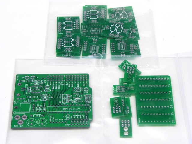
Circuit boards from BatchPCB

I’ll say more about these designs as I work on the projects, but starting at the top and progressing in reading order:

  • Logic gate boards to help bridge the huge gap between what happens in the digital design lecture and lab. My classmates with no prior experience did not gain much academic value from poking opaque ICs into breadboards.
  • A Freeduino-derived board for my personal use, manufactured as a proof-of-concept that I have the right components and schematic to embed an Arduino-compatible core into projects of my own. (I will of course publish all source files for designs that I distribute to anyone other than myself.)
  • The first half of a pair of boards to breakout a headphone cable and jack for breadboarding, to plug an iPod’s headphone output into op-amp filter circuits and listen to the results.
  • A board for testing component lead fit against through-hole sizes. To date, I’ve used calipers for measuring lead sizes for PCB design. I’m curious whether testing against a physical board gives me any different expenditure of time or quality of results.

The logic gate boards were my first batch. I ordered four each of two variants of the boards, assembled a few, and discovered that I don’t like soldering 0603 SMT as much as I thought I did; so if I make more, I’ll be changing the boards to use 0805 components.

Lesson learned: Order only one of your first prototype, regardless of how sure you think you are that you’ve finalized the design.

So why so many of the other boards? I did order only one of each … but SparkFun, bless their hearts, appears to fill wasted space in each panel with small customer boards that they give back to their customers as a bonus; and I happened to have small designs in this batch.
Last Stage of Circuit Board Design: Correcting for the Real World

Sunday, August 21st, 2011

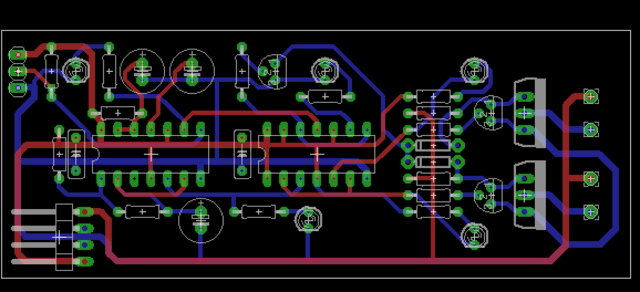
I’m working on a PC board layout for a circuit I’ve built and tested on the workbench. I enjoy board layout, but I was still delighted to be finished with the design. I printed out a copy, not to test whether all the components fit, but to stare at for a day and see whether I found anything that might need to be corrected.

Boy, did I.

Circuit board layout

In general, the first stage of laying out a PCB is placing external interface components — connectors, switches, potentiometers, etc. — followed closely by other large components and power supply traces. For me, the last stage of layout is doing a sanity check that the board will actually work (and be possible to assemble) in the real world.

Here’s what I found.

(more…)

Viewing PCB Gerber Files Before Manufacturing

Thursday, May 6th, 2010

I’ve spent my last week and a half’s free time going back and forth among EAGLE, eagle3d, 1:1 printouts, and the Viewplot Gerber viewer. That’s how long it took me to get the silkscreen layer tweaked to my satisfaction — which I completely didn’t anticipate.

Thank you, thank you, thank you SparkFun for emphasizing how important it is to view your Gerbers before submitting (search in page for “Something I highly recommend”).

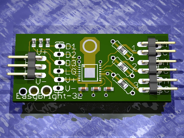
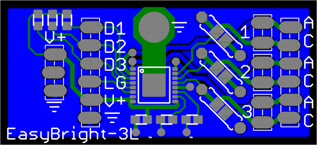
eagle3d view of LED driver prototype

I had already rendered the board layout in eagle3d (pay no mind to the test holes I used to figure out that eagle3d doesn’t make holes through copper that’s part of a polygon, which its documentation clearly states if you bother to read it) and thought it looked pretty good.

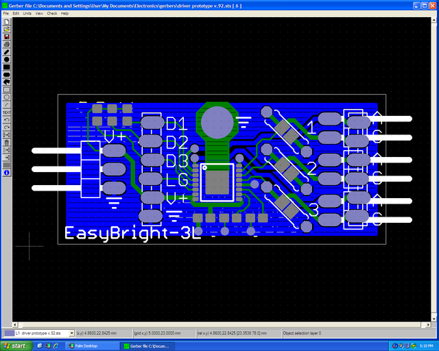
But I followed Nate’s advice, installed Viewplot, and was rather startled to see what my board was really going to look like.

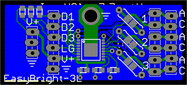
Viewplot Gerber view of LED driver prototype

The silkscreened boxes for the plastic “keepers” on the pin headers are fairly faithful to the connectors I’m using, but what’s with putting the pins in the silkscreen? I don’t need a shadow of the pins on the board.

Also the 0805 SMT resistors and capacitors don’t have silk around them showing which pads belong to the same component. It’s easy enough to figure out on this small board, but I’d like to develop good habits.

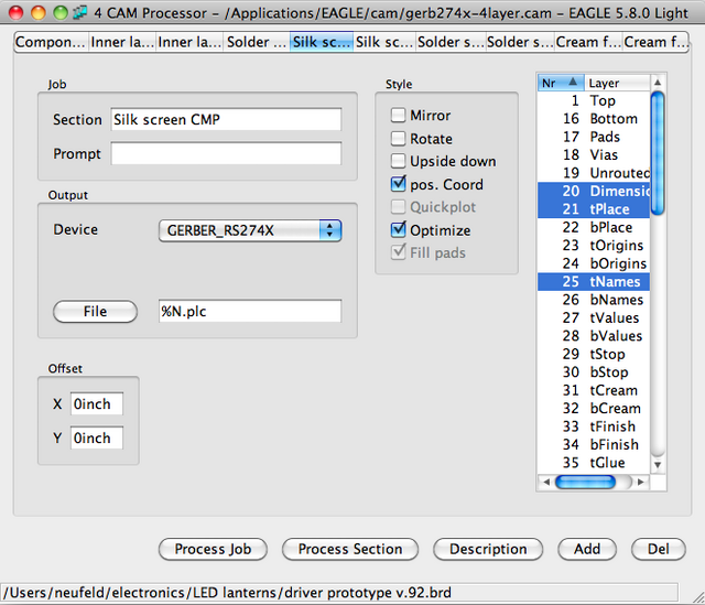
EAGLE CAM processor showing layers going into top-side silkscreen

EAGLE’s CAM processor lets you pick which PCB layers are used to generate each Gerber file, and there’s not much in my top silk layer. The pins must be in tPlace, so I used the PCB layout editor to preview what would happen if I turned it off …

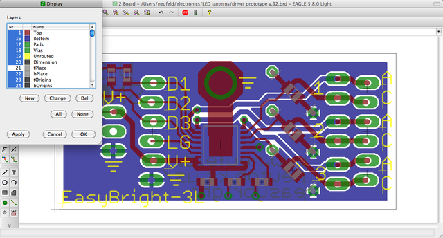
EAGLE PCB layout with tPlace layer switched off

I lost the header outlines as well as the pins, as well as the outlines for the optional through-hole resistors. That’s not gonna work.

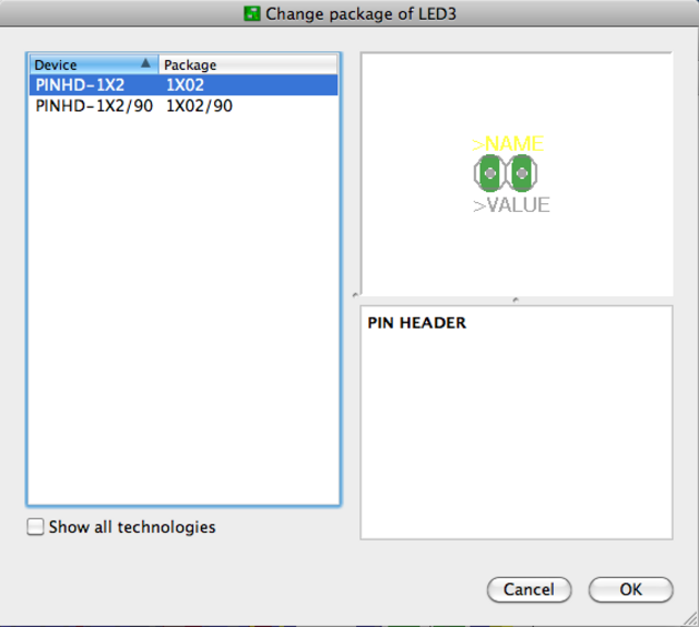
Changing package of two-pin connector in EAGLE PCB layout

Exercising outrageous optimism, I tried changing my header packages from right-angle to vertical, hoping they’d have more appropriate package outlines (still in the tPlace layer).

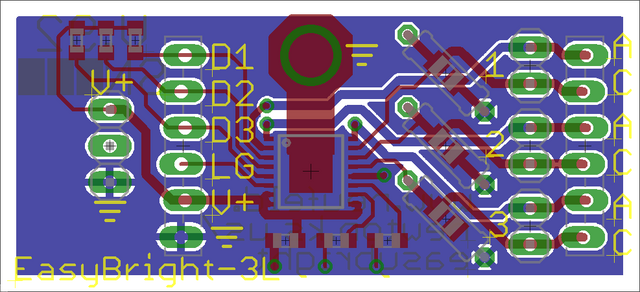
EAGLE PCB layout with header type switched, tDocu on

Better — no stray pins in the silkscreen. Now guardedly optimistic.

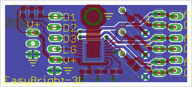
EAGLE PCB layout with tDocu off and supplemental silk drawn in tPlace layer

I turned off the tDocu layer that shows the physical outlines of components, and which isn’t (and mustn’t be) included in the silkscreen Gerber because it would interfere with soldering, then added lines in tPlace to indicate the edges of SMT components.

Silly me — I thought I was done!

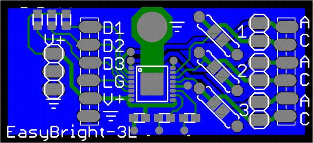
Viewplot Gerber view of revised LED driver prototype

Back in Viewplot, look at how the silkscreen around the power connector is now crowding the pin labels. Aaargh! There’s not room to move them far enough away.

Viewplot Gerber view of revised LED driver silkscreen

I went back to my connector library and designed two- and three-pin versions of “locking” connectors based on the SparkFun locking connector concept. (See footnote about SparkFun EAGLE library license terms.)

The Gerber view looked pretty good now, except the ground symbol was too close to the power header and a little visually confusing.

Viewplot Gerber view of LED driver with working drill holes

I moved that down a bit and in my next trip to Viewplot discovered how to get the drill holes to show up: don’t load the drill rack file into Viewplot, just the drill file itself. Getting visualization with holes and confirmation that there’s really a mounting hole through the heatsink — outstanding!

Somewhere around this time I also printed out the solder-side of the board to make sure that the boxes I made to write in (visible in the next screen shot) were large enough for me to write in. They weren’t. I enlarged them.

Done now, maybe?

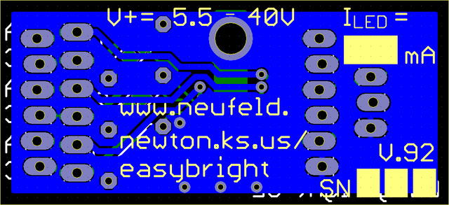
Viewplot Gerber view of LED driver with working drill holes, back

Oof, look at all the problems with the silkscreen on the back side. The top line looks like I’m incrementing V by 5.5-40V (C joke), and if I fix that I need to move ILED‘s = further away also. The / in the URL is awfully close to the solder pad, and the box for me to write the “factory”-configured LED current could stand to extend a little closer to the “mA” label.

Props to Nate at SparkFun again (search in page for “Label everything, all the time”) for reminding me to put the input voltage range and output current rating on the board, BTW.

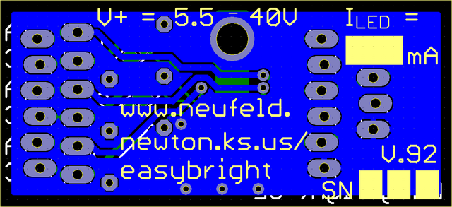
Viewplot Gerber view of final LED driver design, back

Fixed! Really! Done! If I stare at this thing any longer, I’m going to start hand-kerning the vector font.

I zipped the files and uploaded them to Gold Phoenix last night.


SparkFun EAGLE Library License Terms

I’m not using SparkFun’s EAGLE library nor a derivative of their library file because I haven’t got a response from them whether their cc-by-sa license is intended to be:

  • like the GPL, meaning that if you use their library in your board design you have to open-source your whole design — which I will do after I’m confident the design is right but not immediately upon shipping — or
  • like the LGPL and you can use the library in your product without open-sourcing your design but you would have to open-source derivatives of the library itself.

So my connector library is most definitely based on Pete Lewis’s idea to skew pin positioning from side to side to make a header friction-fit in a board for soldering, but (as far as I know) the idea is not patented and I’m in the clear. My library is a reimplementation from scratch of the idea, so is not derivative of their library.

I hate playing games like this and I would love to toss my library and use SparkFun’s if I can get a verdict from them on the licensing. Also as soon as I’ve got boards tested and working and I’m ready to publish the design files, I can switch back to their library too.

Update 07-May-2010: I heard back from SparkFun and it will be fine for me to use their library. I’ll look at switching back on the next iteration of the board.