Archive for the ‘Robotics’ Category

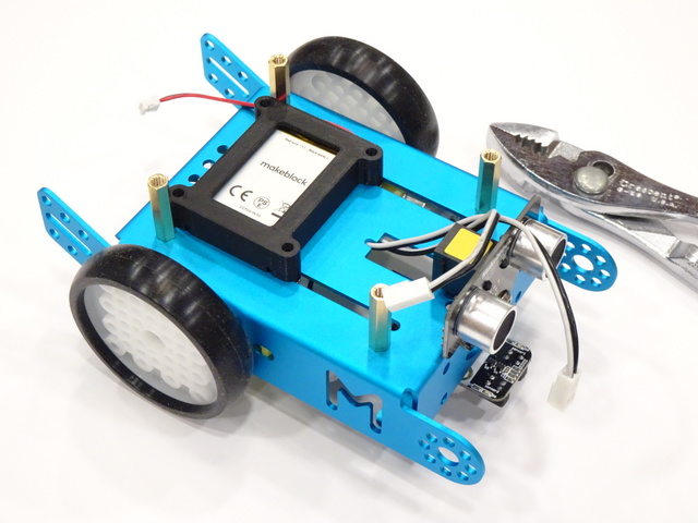
3D-Printed Makeblock mBot LiPo Battery Holder

Wednesday, June 12th, 2019

I’ve assembled a couple of Makeblock mBot robots I picked up a few years back and intend to start programming soon. They come with a 4xAA battery holder, but I’m not a fan of single-use batteries and Makeblock’s LiPo is only $10 on Amazon [no affiliation and not an affiliate link, just a happy customer], so I ordered a couple.

The LiPo batteries came in clear plastic cases with tabs that looked like they should latch into the slots on the robot chassis, but the spacing was off. The robot kit came with hook-and-loop tape to fasten down the battery holder, but yuck. So I designed this holder, which is good enough to use after a single pass of dimensional refinement.

Makeblock mBot robot with 3D-printed LiPo battery holder

Many thanks to my student employee Kip for printing the battery holder on his Prusa I3 MK2s. The quality is outstanding.

I’ll upload the design to Thingiverse after a bit of code cleanup.

(more…)

Modifying a Tower SG90 Servo for Continuous Rotation with Potentiometer Position Sensing, Part 1: Investigation and Continuous Rotation

Tuesday, January 6th, 2015

A common strategy in the world of hobby robotics is to modify a servo for continuous rotation to use to drive the wheels of a tabletop robot.

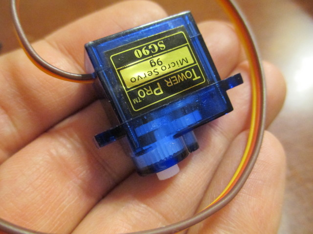
Tower SG90 Servo in hand for scale

On its own, the servo takes power, ground, and a position input and moves the shaft within a range of rotation to match the angle requested on its input wire. It has one or more stops in its gearbox to prevent it from rotating past the end of its range; these need to be removed. It also has a potentiometer as part of its positioning system, which — for the usual modification — needs to be tricked into thinking it’s always centered. The modified servo then runs at full speed forward or backward trying to reach a requested position and thinking it has never succeeded in doing so; and the controller requires extra, external rotation sensing if you want to detect what the servo has actually done so far.

I wanted something a little different — PWM H-bridge control of the servo’s motor for variable speed forward and backward and access to the potentiometer to detect position (crudely and at low speed) and count wheel rotations (acceptably and at high speed). This is actually an easier modification — but, though I’m surely not the first to do it, I’ve not run across it before. I started last night.

(more…)

Rutgers Student’s CupCaked Robot Chassis

Monday, November 23rd, 2009

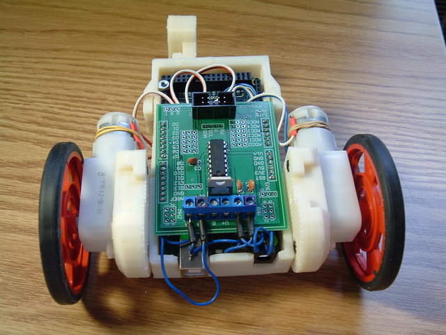
Rutgers student's RepRapBot Mrk II

Being able to do things like this is why I bought a CupCake. via Make

Disappointing Robo-Bug

Tuesday, December 11th, 2007

I went to Radio Shack yesterday for some patch cords and discovered three 3′ MIDI cables for $13. Score! Bought ‘em.

At the checkout counter, they have these cute little motorized bugs for $10.

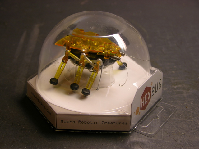
Hexbug in plastic case

I was afraid it’d be lame; but I played with it a bit. When its feelers hit something, it backs up and turns. It sure looked like two motors were being used to control the forward / reverse-turn behavior. Turns out I’m the one who’s lame for getting fooled; but we’ll get to that.

$10 was about my threshold for a bug with two motors and two touch-sensitive antennae. It’d take some tricky rewiring or maybe making a new circuit board, but it should be possible to make the bug a lot smarter. Plus I didn’t really care about the microphone and response to loud noise, and I figured that accounted for a lot of the circuit board, which I could disable or remove.

Plus it’s really compact. The body is only an inch wide and about an inch and three-quarters long; that makes it really cute.

Bought one. Took it apart today.

Pre-Operative Impressions

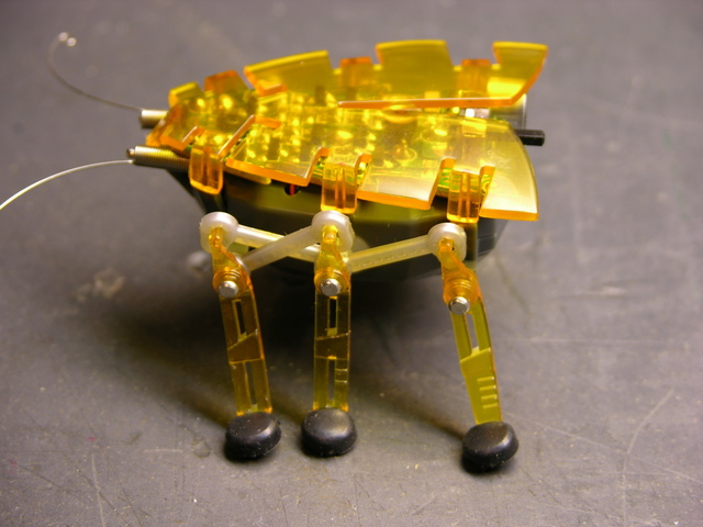
Hexbug standing

The Hexbug is what I call a faux walker — it doesn’t shift its balance to place its center of mass over alternating feet, and each side’s legs only have a single degree of freedom. It’s incapable of falling over, and it could just as well have treads or wheels. It’s still cute — I’m just being clear that I have no delusions about its level of sophistication. Except how many motors it has.

Each side’s legs are powered by a single rotating shaft, shown below. The linkages in the picture above transfer that motion. The front and rear legs move in sync, and the middle leg moves in the same direction but 180° out of phase.

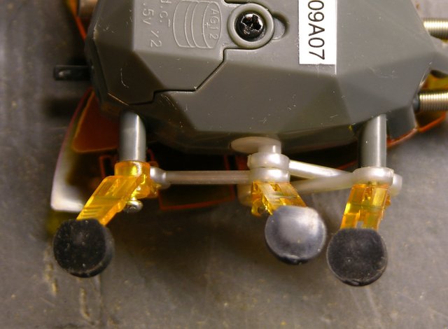
Hexbug motor and linkage closeup

With the bug upside-down, you can see the rotating shaft coming out of the bug body, with an eccentric knob driving the linkages.

The outer legs’ axles are stationary, so the legs just swing back and forth. The middle leg’s axle is attached to the eccentric peg on the rotating shaft, causing the middle leg to move up and down while turning; this is how it lifts its foot to move without dragging.

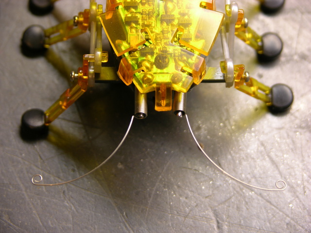
Hexbug antennae closeup

Finally, before beginning disassembly, the antennae are coiled springs positioned around stiff wire, with feelers protruding at the ends. When a feeler presses against something, the coil portion of the spring contacts the wire, closing a circuit and telling the bug to reverse and turn. These are actually more nicely done than other wire feelers I’ve seen — they do a really good job of retaining their shape and position.

Now to Operate . . .

Hexbug standing

The orange wing is press-fitted on, although more tightly than I expected. Each of the six side flaps that bend down, plus one on the front, continues in a peg pressed into a mating hole in the body. I put a flat screwdriver between the PCB and the wing and twisted to loosen each peg, being careful not to crush anything on the PCB in the process.

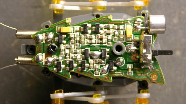
Hexbug PCB

There’s the brain. I haven’t traced the circuit, but I can make a few observations. The solder blobs below and to the right of the grey standoff in the middle of the board are the battery connections, the blobs at the front are obviously the antennae connections, and the blobs in the center of the lower half of the board are the motor leads. Two leads. One motor.

The top of the board looks like it’s audio processing, running from the microphone in the back toward the antennae at the front (since a loud noise and an antenna hit perform the same function) and feeding into the motor drive on the lower half of the board.

Motor and Drivetrain

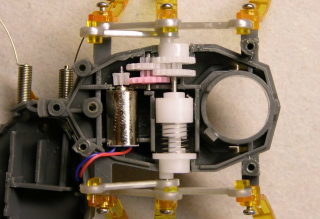
Removing the screw from the PCB and pressing in a latching tab at the back end of the bug (I did it with the batteries already removed, but this might not be necessary) allows the bug’s body to split open, revealing the motor and drivetrain. Motor. One motor.

Hexbug motor, geartrain, and reversing clutch

Look. It’s one motor.

Duh.

The motor leads aren’t very long, so the upper half of the bug is tucked under the front end of the lower half of the bug in this pic.

When the motor is turning “forward” and the white gear at the top of this picture (right-side legs) is moving with its upper teeth going forward, the coil spring at the center is being turned in the direction that makes it “unwind” and expand in length. This forces the cam at the bottom of this picture (left-side legs) to turn with.

When the white gear at the top is moving with its upper teeth going backward, the coil spring is being turned in the direction that winds it tighter, making it contract. This releases pressure against the bottom cam and causes the spring to slip against it instead of forcing the cam to turn.

What Next?

So now I don’t know what to do with this dumb bug.

  • Be a good little consumer and let it wander around my desk until its batteries die or it falls off and gets crushed. Not my style.
  • Mod it for two motors somehow — stick another motor in (hard!) or buy another bug, rip the left legs off both of them, glue their left sides together, and have a double-wide bug with two motors. But that’d require another $10 bug, and one $10 was the max I’d spend for a two-motor bug.
  • Figure out something else cool to do with it. Dunno what.

OR

  • Give it a smarter behavioral system that, within the capabilities of its lameness, emulates a two-motor bug.

The last one is actually kind of intriguing. Right now, when it hits an obstacle, it backs up enough to do about 90° of clockwise turn, regardless of which antenna made contact. So “reprogram” (rewire) the bug to discern which antenna was hit and turn 90° CW or 270° CW accordingly. Because it rotates about its left legs rather than its center, 270° CW is not the same as 90° CCW would be, but it’s as close as we can get.

With a tiny microcontroller on board, it could get more sophisticated yet, turning at other angles, and even doing quick reverses during normal forward travel in order to move in forward curves.

Thoughts?

Making Googly Eyes, Part 2: Construction

Monday, April 16th, 2007

As noted in Googly Eyes Part 1, I built a demo back in February out of a CD-ROM drive optical sled assembly and a couple of ping-pong balls. In the earlier installment, I discussed reverse-engineering the sled’s electrical connections; now here’s how I rebuilt it to operate eyeballs.

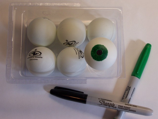
I had thought I might find some googly eyeballs in the Wal-Mart craft department, for making big puppets or something. But all their googly eyes were the flat, button-like kind that just stick onto a surface, so I went with my fallback plan of ping-pong balls.

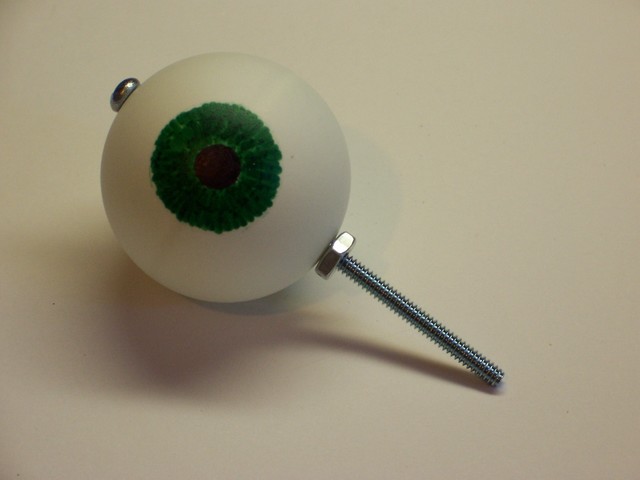
Drawing an eye on a ping-pong ball

I drew an eye onto two of them, with a black pupil and green iris. I didn’t mean to get the iris quite so dark, but at least I made it with radial lines.

Googly eye with bolt for axle

I located and marked the north and south poles of the ping-pong ball as carefully as I could, then drilled through with PCB drill bits. After stepping through several increasing sizes, I was able to use my stepped drill bits to make nice, round, even holes for the axle. I stuck a bolt through and threaded a nut up fairly close to the ball, so it could swivel but not move up and down much.

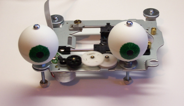
Googly eyes mounted to frame, front view

The sled assembly didn’t have the right sized holes in the right places, so I used big fender washers to make things fit. The eyeball-mounting nut is tightened against the fender washer, with another washer and nut on the bottom side. The bolts continue through the frame and act as legs to raise the underside of the carriage off the surface it’s sitting on, with cap nuts (acorn nuts) for feet to keep the end of the bolt from scratching.

This was actually a bit less than ideal, because the mounting hole for the right eyeball (left edge of the picture) is in a section that’s bent up and raised above the plane of the other holes. I tried compensating for the height difference with an extra nut under the left eyeball, but it’s still not quite right. Probably a washer in between the two nuts would fix it up.

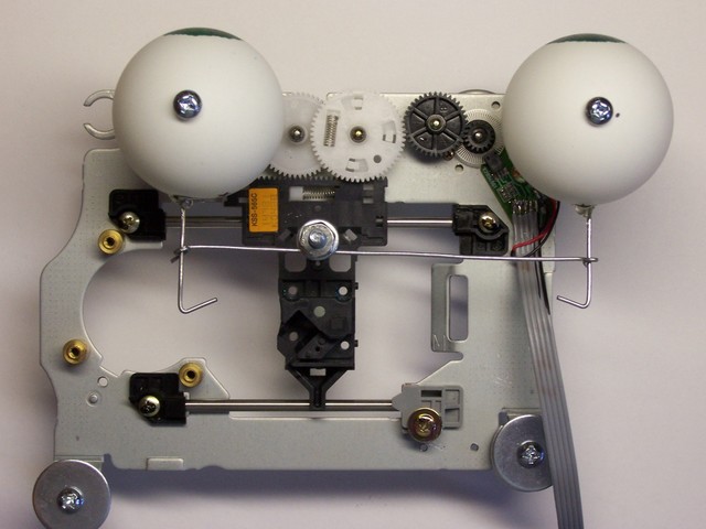
Fully-assembled googly-eyes mechanism, top view

Finally, I needed to translate the sled’s linear motion into the eyeballs’ rotary motion. I turned a loop into the end of a couple of pieces of stiff wire, and . . . had to take the eyeballs back apart again. I drilled another hole in the back of each one, then pushed the wire loop into the interior and reassembled them with their bolts going through the wire loops. Once reassembled, I dabbed some hot glue where the wires came out of the eyeballs; now I could use the wires as control rods to rotate the eyes.

I removed all the optical parts from the carrier sled, then ran a bolt up through it to the height of the eyeballs. I made a loop in the center of another piece of wire and sandwiched it between two nuts on the sled bolt, then made a loop at each end around the eye control rods. After a little tweaking of the angles, I got it set up for fairly smooth movement, with the ends bent to keep things from slipping out of the loops.

In Part 3, I’ll discuss the software that moves the motor and watches the optical disk to monitor travel.

PWM Control of a Larger DC Motor

Saturday, April 7th, 2007

A year or two ago, I bought a couple of cheap cordless drills at Harbor Freight with thoughts of tearing them down to use the motors for MOSFET-controlled robot drive systems. Yesterday in lab, several guys were talking about how to control DC motor speed for their final project. Serendipity kicked me in the butt and got me prototyping.

The Circuit

The obvious approaches to varying DC motor speed are varying the supply voltage and varying a resistor in series with the motor (which amounts to the same thing). The problem is, DC motors don’t run well on a low supply voltage, and the response is very non-linear.

The usual solution is to use pulse-width modulation (PWM): turn full power to the motor on and off rapidly, increasing (modulating) how long the power is on (pulse width) to increase the motor speed, and decreasing the pulse width to decrease the motor speed. And the PIC (the underlying hardware of the LogoChip) has built-in PWM control, because it’s designed to be used for a wide variety of applications just such as this.

The LogoChip/PIC can’t supply enough power to drive a large motor, so the total control circuit involves a LogoChip, a MOSFET power transistor, and some “glue” circuitry to interface the two together.
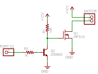
MOSFET motor speed control schematic

If I’d been building the circuit on a breadboard, I’d probably have started by plugging in components and wiring them up, because mistakes are easy to correct by unplugging and replugging. But since I was using larger components that I was going to need to solder, I didn’t want to have to change too many connections; so I started by drawing the schematic I intended to build.

(First I reread my May 2006 post about driving stepper motors with MOSFETs. They don’t use the same circuit, but I had taken the time to review my textbook and figure out how to treat MOSFETs right; and my blog isn’t just for y’all–it’s secondary storage for my own memory.)

The PIC’s PWM output is on port C2. The MOSFET’s gate needs at least 7V to saturate (turn all the way on), so port C2 controls the base of an NPN transistor (any common NPN will do; I happened to have a 3903) that switches the MOSFET gate between 12V and ground. The N-channel MOSFET in turn provides a ground path to turn on the motor when the MOSFET’s gate voltage is high.

The only snag is that the bipolar transistor inverts the control logic; so when C2 is high, the motor is off; and when C2 is low, the motor is on. Oh well. We’ll compensate in software.

Wiring it Up

I started by bolting one of my IRF510 MOSFETs to a heatsink. I should have used thermal grease, but I didn’t have any handy and I’m doing a quick test. And I should have used an insulator (since the FET’s tab is wired to drain, and that’s not going to be ground, and the heatsink might bump into something that’s grounded), but the heatsink seems to be anodized and sorta insulated already and I’m just doing a quick test.
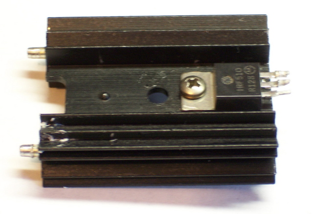
MOSFET mounted to heatsink

I could have used the cordless drill’s battery to power the motor, but I didn’t feel like rewiring that much of the drill right now. So I settled on using my trusty old PC power supply–and I desoldered a connector from a dead CD-ROM drive to mate with the power supply. (Bench vise, heat gun, and pliers.)
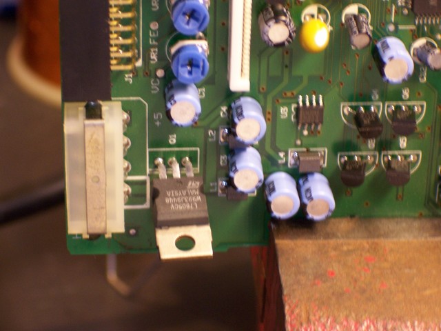
Molex power connector on CD-ROM drive board

I wired the MOSFET to the power connector and left fly wires to go to the motor and the LogoChip. As always, I put heat-shrink tubing on each solder joint to be safe. The 10K pull-up resistor at the end of the blue wire, hidden behind the yellow wire next to the power connector.
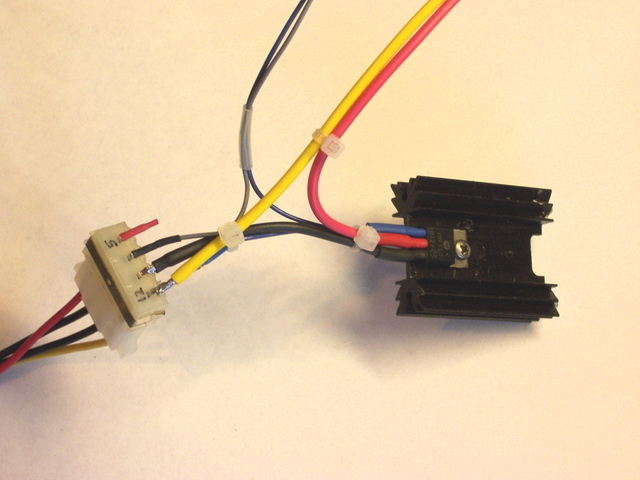
Fully-wired MOSFET and power connector

The 5V supply on the power plug isn’t needed, so I insulated it as well.

Connecting the Drill

The largest DC motor that I could think of having at home was the cordless drill. It’s not as big as the windshield wiper motor that Team Doccia might be using, but it’s the best I could do. Here’s the victim with its the case removed:
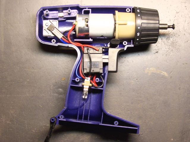
Cordless drill, case opened

The motor is the silver and white cylinder in the center of the top of the picture. The tan cylinder to its right is the planetary gear system that reduces speed and increases torque.

To the left of the motor, you can see the MTP15N06V MOSFET that normally runs the drill. I could have reused it, but (1) then I’d have been done before I even started; and (2) I wanted to test with a FET that I had lots of, so someone else could use exactly the same circuit. Both the drill’s MTP15N06V and my IRF510 have a built-in reverse-biased diode to shunt the back-EMF spike that occurs when the supply voltage is removed from an inductive load (like a motor).
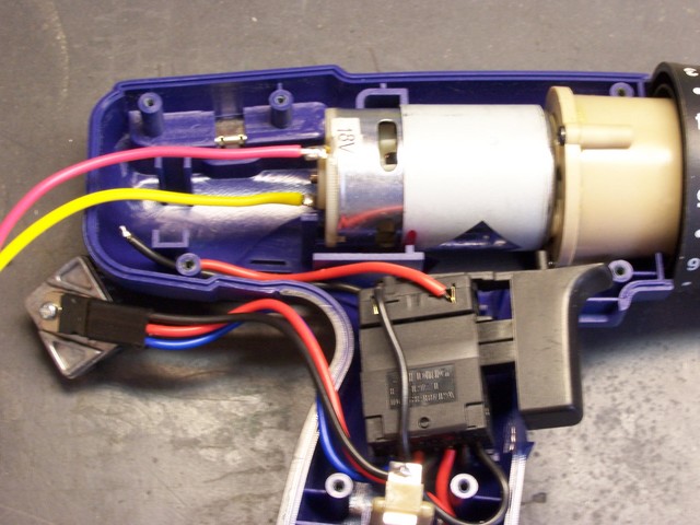
Cordless drill motor rewired for MOSFET speed controller

I pulled the the motor out of the drill casing, soldered on the leads from the FET wiring harness, and jammed it back in. I could have laid in on my bench for testing, but I was afraid the counter-torque when the motor started up at high speed might roll it right off the edge. The gearbox has a tab on the bottom that mates with the case and keeps it from twisting.

LogoChip Wiring

Tom left a nice prototyping area on the LogoBoard when he designed it, so I built the rest of the circuit there. I soldered a header socket into the connector for pin C2, plugged the NPN transistor into the breadboard section, and plugged in the base resistor and the gate and ground leads from the FET assembly.
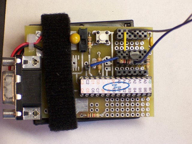
LogoChip NPN switching circuit

Here’s what the whole works looks like when it’s all hooked up:
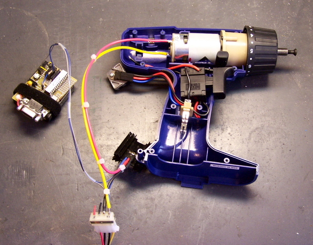
Cordless drill motor wired to MOSFET speed controller

Control Software

For prototyping, I reused my old motor-pwm-demo.txt program, even though it has some extra stuff that’s not needed here. I called pwm-init and then pwm-set 255 255 to shut the motor off. (Remember, it’s backwards logic because of the inverting effect of the NPN switching transistor.) pwm-set 255 0 turned the motor on at full speed, and pwm-set 255 128 selected a medium speed. pwm-set 255 196 was about as slow as it could reliably go.

To explain the code, the first parameter (the one that I’m always calling with 255) is the period of the control pulse–the higher the number, the longer between consecutive pulses (i.e. the slower the pulse train). The second parameter is the pulse width–how long each pulse output should be on. So pwm-set 128 64 should have about the same effect as pwm-set 255 128, only twice as fast (half as long).

Unfortunately, that ain’t quite so. Due to the inductive effects of the motor coils, some frequencies of PWM control work better (more efficiently) than others. In this case, the lower control frequency is more efficient–the motor runs a little faster at 255/128 (longer pulse = lower speed) than at 128/64 (shorter pulse = higher speed).

Worse, the motor would probably like it even better if the control frequency were even lower. But I can’t do that–I’m already running the PWM clock at its lowest speed and dividing that speed as far down as it goes. This is as good as it gets.

Final Thoughts

Motor On at Powerup

When the circuit powers on, port C2 is set as an input, so the MOSFET’s pull-up resistor pulls the line high and the motor turns on at full speed. That’s bad; you never want mechanical systems initiating motion before the control systems come online.

The circuit should really be redesigned to use non-inverting buffers to get around this problem. But for now, at a minimum, the motor should be turned off in the LogoChip’s powerup routine:

to powerup
pwm-init
pwm-set 255 255
end

Operating Temperature

With an ambient temperature of 72°F, the FET got up to about 96°F after running for a few minutes. The FET is rated for 250°C and its rated capacity only drops from 5.6A at 25°C to 4A at 100°C, so it’s well within safe operating conditions. If a larger load were required, I might look at using more FETs in parallel. (I don’t even remember whether you can do that, so I’d start with the Malvino textbook and review whether parallel FETs are subject to thermal runaway.)

Low Torque

The drill really doesn’t have much torque using this driver at low speeds. Granted, the drill is rated for 18V and I was running it 12V. But I was hoping to get away with using open-loop control for robotics, and it looks like I’ll probably have to put optical encoders on the wheels to make sure they’re really turning as fast as I told them to.

I’m still optimistic that a windshield wiper motor is geared down enough, and natively runs at a low enough speed, that this control method will be adequate for Team Doccia’s breathing mechanism.
Making Googly Eyes, Part 1: Reverse Engineering

Monday, April 2nd, 2007

Back in mid-February, I wanted to demonstrate motor control with the LogoChip to class, but it’s hard to see what a motor is doing unless it’s geared down and attached to something. I decided to make googly eyes that could look around, and here’s how I went about it.

Motorized googly eyes

CD Read Sled

Although the motion of each individual eye is rotary (right to left; these can’t look up and down), to synchronize their actions, I needed linear motion.

Digression: Predator species have eyes on the front of their face, to triangulate the distance to their target. Prey have eyes on the sides of their heads, to keep the widest possible view of their surroundings and watch out for predators. Predators’ eyes generally move in synchronization. Of course, they may look slightly inward when watching a nearby object (binocular convergence; think of looking cross-eyed at your nose); but for a simple model like this, two eyes always looking in exactly the same direction is adequate.

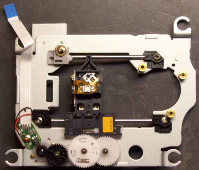
I figured my best shot was something from a dead CD-ROM drive, so I went down to examine my stash. What I call the read sled assemblies looked the most promising–they’re the ones that move the read head in and out along the radius of the disc to find the right position to play. The tray motors might also work, but the trays have a good 5″ range of motion. The ∼2″ range of the read sled seemed much more useful.

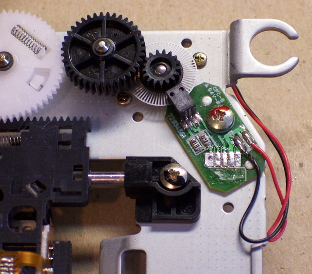
Several of the assemblies I examined used a stepper motor, but I wanted to demonstrate a simple DC motor, so I kept looking. Finally I came across this one, which had a DC motor (on the underside), a nice geartrain, and an optical encoder (the faint grey circle between the green PCB and the medium black gear) to determine the position of the sled.

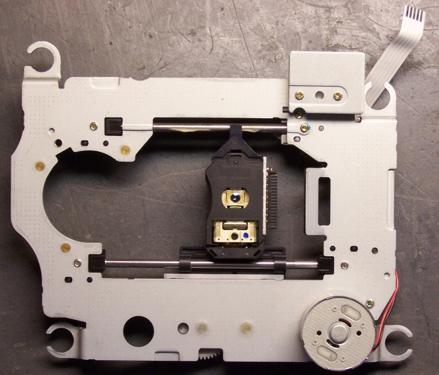
CD-ROM drive read sled assembly

The motor was mounted from the back side, and the optical disk was press-fitted to its shaft.

CD-ROM drive read sled assembly, reverse

Reverse-Engineering the Optical Assembly

I was interested in trying to reuse the optical assembly so that I too (well, my program) would know where the sled was, so I desoldered the flex pcb ribbon cable and set about figuring out the connections on the PC board.

Optointerruptor and interface PCB

The larger black rectangle that overlaps the optical disk was obviously an optointerruptor–one side has an LED and the other side some kind of optical sensor. When a hole in the disk passes between them, light is transmitted; when a bar passes between, the light is interrupted, and the receiver can tell the difference.

The two smaller black rectangles (southwest of the screw head) are surface-mount resistors, reading “181″ (180Ω) and “752″ (7.5KΩ). I could visually follow some of the traces (the light green lines) on the board, but I got lost with exactly what happens underneath the resistors.

I assigned numbers to the five solder pads from the cable, arbitrarily numbering from the outer edge of the board. (In retrospect, that was incorrect–the pad to the left in this photo is shaped differently than the others; that makes it pin number 1. Ah well.) Then I made this table (actually edited here on my blog–all the notes have been sitting around for six weeks, and it’s only the narrative that I’m adding later) describing where each pin went, to the best of my visual acuity.

Pin Connection
1 motor black wire
2 motor red wire
3 interruptor
4 interruptor end of 7.5KΩ resistor
5 both resistors

Pins 1 and 2 obviously run to the motor, and it was pretty clear that they didn’t have any connections to pins 3-5. So I used my ohmmeter to measure the resistance in each direction between each pair of pins out of 3-5. I got this:

4 → 3: 50KΩ
3 → 4: ∞
5 → 3: 40KΩ
3 → 5: ∞
5 → 4: 7.5KΩ
4 → 5: 7.5KΩ

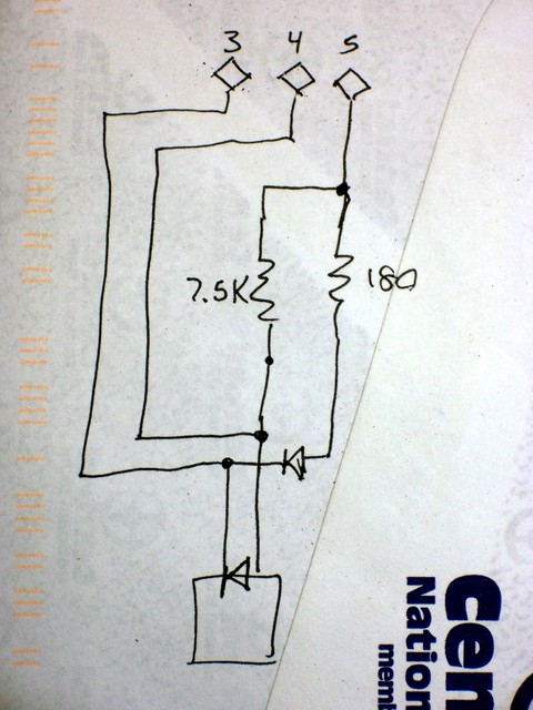
It was obvious that pins 4 and 5 were connected directly via the 7.5KΩ resistor. It was also apparent that there were diodes from pin 4 to 3 and from pin 5 to 3. That gave rise to this diagram:

CD read sled connection diagram, reverse-engineered

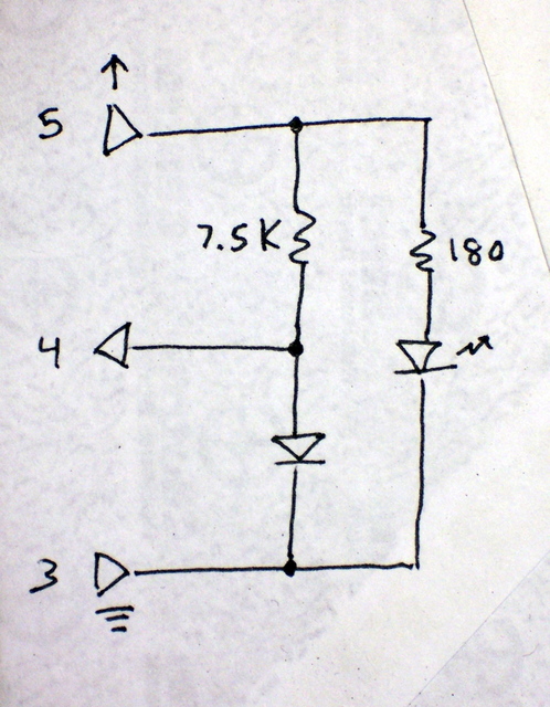
Which made a lot more sense once I redrew it like this:

CD read sled connection diagram, redrawn

Pin 5 is the supply voltage, pin 3 the ground, and pin 4 the readout of the voltage divider between the 7.5KΩ resistor and the photosensitive diode. Voila!

Using the Optical Encoder

A 180Ω current-limiting resistor with a 5V supply would give ∼24mA of current through the LED, and that seemed a little high. I’m guessing that part of the circuit ran on 3.3V, making the LED current ∼14mA–a more reasonable value.

I wanted to shoot for 15mA, so 4.3V / 15mA ≅ 290Ω, of which 180Ω was already in the circuit, leaving 110Ω to add. I had a 120Ω resistor in my bin, so 4.3V / (180Ω + 120Ω) ≅ 14mA, which was close enough. I used the 120Ω resistor to wire pin 5 to the 5V supply, placing it in series with both diodes. (I figured its impact on the 7.5KΩ resistor and photodiode whould be negligible.)

Turning the encoder wheel very slowly and carefully and reading the voltage at pin 4 yielded a minimum voltage of .77V and a peak of 3.4V. (Alas, I don’t remember which was when the light was blocked and which when it was passed . . . probably the photodiode conducted and pulled it down to .77V when light was passing . . . but I don’t know that I really care.)

I didn’t really want to have to use an A/D converter input and deal with a 10-bit numeric value when all I needed to know was whether the light was blocked or passing. But I wasn’t wild about feeding a continuously varying analog voltage into a TTL input–it tends to make them overheat. Happily, the PIC datasheet (p. 102) revealed that pin A4 has a Schmitt trigger input, and my problem was solved.

A Schmitt trigger has hysteresis–the input signal has to rise above a certain point (the “high-water mark”) before it reads high, then fall below a lower point (the “low-water mark”) before it reads low. It’s intended for reading digital values from analog signals, it was exactly what I needed, and it worked exactly as desired. I fed the optointerruptor signal into A4 and got clean, predictable digital results.

Next Steps

That’s probably long enough for one post. Next: Building the eyeball assembly and programming the motor.

Ultrasonic Rangefinder, Part III: Receiver / LogoChip Interface Attempt

Wednesday, April 26th, 2006

I haven’t touched the DIY rangefinder project for a couple of weeks, but I realized I also never wrote up my latest work on it.

Receiver Comparator

After my previous post about building two amplifier stages, I intended to use one of the spare channels on the LM324 as a comparator to “digitize” the amplified receiver signal and provide a clean input to the LogoChip. Unfortunately, the first time I prototyped it was late in the evening when my brain doesn’t work too well, and I built it just like the first two stages–as a linear amplifier. I was really surprised to see more analog waveforms on my scope when I expected sharp edges. At only 24kHz, I didn’t think it should be a slew rate problem, but I wasn’t thinking clearly and just set it aside for the night.

The next day, my error was obvious, and I pulled out the feedback resistor to let the op amp run open loop with infinite gain. It cleaned up the signal, although still not as much as I would have expected. Once the basic circuit was working, I replaced the fixed voltage divider with a 20k trimpot and tuned it as well as I could, trying to find the sweet spot to weed out all the noise but pass all the real signals.

I hadn’t seen it before, but now I wondered whether I was getting some false readings from noise, as John suggested he had encountered when working on similar circuits. I looked briefly at adding a low-pass filter to the circuit (it’s already high-pass filtered by the capacitive coupling from the receiver to the first amplifier stage due to the single-ended op-amp I’m using), but haven’t done it yet. First I wanted to connect it to the LogoChip and see what kind of results I got.

PIC CCP

An ultrasonic rangefinder measures distance by emitting a “ping” and counting the time until the echo is detected; dividing by the speed of sound translates the round-trip time into a distance. Because of the short durations involved, the easiest way to do this on a PIC microcontroller is with the “capture” section of the Capture/Compare/PWM (CCP) subsystem. It uses a high-resolution timer and interrupt circuitry to give a very precise measurement of how long something takes to happen.

I started with John Harrison’s CCP code from his srf_demo.txt example on the TechArt wiki LogoChip with Ultrasonic Sensor page. His code was using the PIC’s CCP module #1; but in my application, I was already using CCP1 to provide the 24kHz signal for my transmitter, so I started translating to use CCP2. The control and behavior of the two CCP channels are rather different, so it wasn’t a matter of simple substitution. Here’s what I ended up with:

Here’s the receiver section of the code:

;------------------------------------------------------------------------------
;   Routines for manipulating CCP2 and timer 3 for capture.
;------------------------------------------------------------------------------

constants [
    [CCP2CON $fba]                      ;   capture/compare/PWM 2 control reg
        [CCPxM-CAP-EVERY #0100]                 ;   capture every falling edge
    [CCPR2H $fbc]                       ;   CCP 2 register low byte
    [CCPR2L $fbb]                       ;   CCP 2 register low byte
    [PIR2 $fa1]                         ;   peripheral interrupt request 2
        [CCP2IF 0]                              ;   timer 3 interrupt bit
    [CCP2-PORT portc]                   ;   uses portc pin 1
        [CCP2-BIT 1]
    [CCP2-DDR portc-ddr]

    [T3CON $fb1]                        ;   timer 3 control register
        [T3CCP2 6]                              ;   timer 3 CCP mode bit 2
        [T3CCP1 3]                              ;   timer 3 CCP mode bit 1
                                                        ;   1x src CCP1+2
                                                        ;   01 src CCP2
        [T3CKPS1 5]                             ;   timer 3 prescale bit 1
        [T3CKPS0 4]                             ;   timer 3 prescale bit 0
                                                        ;   11 = 1:8
        [TMR3ON 0]                              ;   timer 3 enable bit
    [TMR3H $fb3]                        ;   timer 3 high byte
    [TMR3L $fb2]                        ;   timer 3 low byte
]

;   Initialize CCP by configuring timer 3 and enabling capture mode.
to ccp-init
    write CCP2CON CCPxM-CAP-EVERY       ;   config to capture every falling edge

    clearbit T3CCP2 T3CON               ;   set T3CCP to 01 to make T3 src CCP2
    setbit T3CCP1 T3CON                 ;       and T1 src CCP1

    setbit T3CKPS1 T3CON                ;   set T3CKPS to 11 to use 1:8
    setbit T3CKPS0 T3CON                ;       prescalar

    setbit TMR3ON T3CON                 ;   enable timer 3

    setbit CCP2-BIT CCP2-DDR            ;   set CCP2 (RC1) pin for input
end

;   Record starting value of timer 3 and clear capture flag.
global [ccp-before]
to ccp-start
    setccp-before ((read TMR3H) * 256) + read TMR3L
    clearbit CCP2IF PIR2
end

;   Wait for capture event and return duration.
global [ccp-after]
to ccp-wait
    waituntil [testbit CCP2IF PIR2]     ;   wait for capture interrupt
    setccp-after ((read CCPR2H) * 256) + read CCPR2L
    output ccp-after - ccp-before
end

I added code to send a ping and take a measurement:

;------------------------------------------------------------------------------
;   Top-level routines to tie it all together.
;------------------------------------------------------------------------------

;   For the sake of testing, activate on powerup.
constants [[standalone 0]]
to powerup
    pwm-init
    ccp-init
    if standalone [ pwm-on ]
end

;   Send a short burst of tone.
to ping
    pwm-on
    mwait 1
    pwm-off
end

;   Ping and measure time to reply.
to range
    ccp-start                           ;   record start time
    ping
    output ccp-wait                     ;   wait for echo and return duration
end

Wrote a little loop to display the results on the PC, and was disappointed to see that they really didn’t vary at all in proportion to the distance from the sensor to an obstacle. After a few minutes of head-scratching, I noticed that I hadn’t wired the comparator output to the LogoChip’s CCP input. Oops! And that’s when I realized I had a much bigger problem.

Overloading Port C1

The PIC’s CCP modules are implemented in hardware, and they’re hard-wired to specific pins. The input pin for CCP2 is the same as general-purpose pin C1–in fact, most if not all of the PIC’s pins have multiple functions that are selected by configuration registers.

My problem arose because C1 is already being used by the LogoChip firmware–as the Go/Stop input! Because LogoChip Logo isn’t open-source, I can’t see exactly how it’s being used, and have to guess what would happen if I tried to use it as a capture input. Since pressing a button attached to that pin makes the LogoChip stop executing user code and return to an idle state, I can’t imagine I’d have an easy time overriding that behavior and getting it to use the pin solely for CCP with no interference.

So what now? I need both CCP modules–one to use the PWM output to drive the 24kHz transmitter, and the other to watch and count time on the receiver. I don’t think I’ll be able to overload C1 with CCP2 for the receiver, so I’m left with a couple of options: swap the pins, or use CCP1 for both transmission and reception.

Swap the Pins

My first thought was to use CCP1 as the receiver (since its corresponding port, C2, is otherwise unused) and make CCP2 the transmitter (on port C1, the Run/Stop button). John says he has previously overridden C1 and used it as an output when the Run/Stop functionality wasn’t needed, so this should work.

In the long run, though, I’m a little uncomfortable giving up the Run/Stop button. I’d like to be able to integrate this technology into hobby robots, and I’d like to be able to leave them powered up but in an idle state, without having to duplicate the preexisting Run/Stop behavior myself in software. Swapping the PWM-transmit / capture-receive pins should work for a quick fix, but I’m not sure it’s where I want to be in the larger game.

Use CCP1 for Both Transmission and Reception

Alternately, I could overload CCP1 for both transmitter and receiver. There’s precedent–another student in class is using the Parallax PING))) (TM) sensor module, which has only three pins–ground, power, and bidirectional signal.

To do that, I’d need to make sure that transmission and reception don’t interfere with each other. Keeping transmissions out of the receiver circuit is easy–put a diode from the comparator output to the LogoChip so the transmitter signals don’t go “upstream” into the comparator.

Keeping comparator signals out of the transmitter driver is a little trickier, but I think I have a reasonable solution, based on something I was considering doing anyway. I’d like to be able to drive multiple sensors from one LogoChip, but there’s only one (er, two, maybe, sorta) PWM output available. To drive multiple rangefinders, I’d need to multiplex the PWM signal somehow–and there are plenty of ways to do that.

The most straightforward is to use a few LogoChip output pins to select which transmitter to drive and AND (or NAND) them with the PWM signal. Cake! And it tidily solves my receiver-interfering-with-transmitter problem–the receiver can dump whatever it wants onto the PWM output, but it won’t go anywhere harmful unless one of the transmitter select lines is activated.

Sounds like a win all around, and I think I’ll investigate it as soon as things calm down with the exhibit and I can get back to tinkering. It means a little more work on the software side (switching CCP1 back and forth between PWM and capture modes), but I’ve never been afraid of writing code.

Ultrasonic Rangefinder, Part II: Receiver

Sunday, March 26th, 2006

Last night, I prototyped the transmitter circuit; today, I worked on the receiver. Coe’s design uses a two-stage op-amp circuit, with AC coupling on the input from the transducer to the first stage, to amplify the received signal before sending it to a comparator. I wanted to do the same, but I prefer to run from a single supply voltage, so I used an LM324 and added voltage dividers to bias the signal up to 2.5V.

First, I powered up the circuit from last night and measured the receiver’s signal on my scope. With the transmitter and receiver about 2” apart, the receiver signal was about 2V peak-to-peak, attenuating to about .5V p-p at 2’. If it continues to attenuate by a factor of 10 every 2’, then to measure distance out to 10’ (round trip of 20’), the received signal would be 2 * 10-10, or .2nV. Let’s hope that’s not the case!

The Circuit

Each stage of the amplifier circuit is taken directly from the LM324 datasheet, “AC Coupled Inverting Amplifier” (although the two stages are DC coupled). The receiver’s signal is AC-coupled to the first amplifier’s inverting input, with a 2.5V bias to the non-inverting input.

Ultrasonic Receiver Amplification Schematic

I’m not sure why C1 is needed on the bias voltage divider, but the output waveform was considerably cleaner with it than without, so I left it in. I also don’t know what RB does, and Forrest Mims’ Engineer’s Mini Notebook on op-amp circuits didn’t show it but the datasheet did, so I left it in as well.

Values

The bandwidth-gain product for the LM324 is 1MHz, so a 24kHz input means the maximum possible gain is about 41.7. The gain is set by the quotient of the feedback and input resistors, and it worked very naturally to select RF = 1MΩ and RIN = 24kΩ.

According to Mims, CIN should have a value of 1 / (2π flow RIN), where flow is the lowest frequency to pass the filter. This gives CIN = 1 / (2π 24kHz 24kΩ) ≅ 280pF–except the first time around, I mistakenly calculated using RF (1MΩ) instead of RIN (24kΩ), and got 6.6pF. I had a 10pF on hand, so I substituted it; but it was still far too low a value, as will be seen shortly.

I breadboarded the circuit on my workbench and measured about .04V peak-to-peak directly from the receiver element, with both transducers pointed at the ceiling. (That was about an 8’ round trip, so my dire prediction of .2nV was fortunately not the case.) Next, I measured only about .08V p-p at the output of the first amplifier stage, so obviously something was wrong. It was at this point that I added C1, which brought the amplifier output to about .1V and cleaned it up dramatically–but with a gain of 40, it should have been more like 1.6V.

I was suspicious about the value of the AC coupling capacitor, CIN, and began substituting different values for it, with the following results:

Condition Signal Amplitude
direct transducer output .04V
CIN = 10pF, C1 absent .08V
CIN = 10pF, C1 = 10uF .1V
CIN = 100pF .5V
CIN = 1nF .6V
CIN = 10nF .6V

It looked like I must have miscalculated by an order of magnitude (at this point, I hadn’t yet caught my frequency error in the calculation), and 100pF was probably close to the best valued, but still a little too far down the knee of the filter’s response curve. .6V output was still a little low for a gain of 40, but within a range I was willing to accept, given that I was estimating the values by counting hashmarks touched by a dirty, wiggling waveform on my scope. I put the 1nF back in and called it good.

Second Stage

After honing the values on the first stage of amplification, the second stage was easy–just more of the same. I used all the same values, but omitted the AC coupling capacitor, since I’m happy to DC-amplify around the 2.5V bias. The second stage gives me a trapezoidal waveform (clipping both the top and bottom of the transducer’s sine wave) running rail-to-rail of the LM324′s advertised output capacity–from 0V to about 4V. Tomorrow I need to run that through a comparator to clean it up just a little more, and then steal John’s capture/compare LogoChip code to start timing the echoes.

DIY Ultrasonic Rangefinder

Saturday, March 25th, 2006

Ultrasonic rangefinders detect objects and measure distance the same way as a bat: Emit a high-pitched “ping” and measure how long it takes the echo to return. The speed of sound in air is nearly constant (ignoring slight variations due to air pressure and humidity), so the time from ping to echo translates directly into the distance to the object.

I’m interested in ultrasonic rangefinders for both hobby robotics and our TechArt final project. They’re available commercially, but $25 each adds up pretty fast if you need multiples to establish a view all around a bot or across the wide front of an art installation. All Electronics has transducer elements for $1 each in quantities of 10 or more, so I ordered a batch of them in hopes of building a rangefinder myself. At $2 each (two transducers, for send and receive), I can add a fair bit of supporting circuitry before hitting the $25 mark.

The Plan

I’m basing my circuit on a design by Gerald Coe at http://www.robot-electronics.co.uk/htm/srf1.shtml, and adapting it for different design goals. His circuit uses a dedicated PIC to provide the oscillator, a MAX232 to generate 16V to drive the transmitter, and 40kHz transducers. For now, I want to run my rangefinder from an existing LogoChip that’s also doing other work, avoid the complexities the MAX232 adds, and use transducers with a different nominal frequency. Later, I might build separate modules intended to stand alone and run with very low power.

Initial Testing

According to a comment on the All Electronics page for the transducers I ordered, they run at 24kHz. The first order of business was confirming that operating frequency.

I hooked my function generator to my frequency counter and scope and dialed in 24kHz, to make sure I was in the neighborhood before connecting the transducer. I then connected one transducer to the function generator to serve as the transmitter (with the frequency counter still attached), and the other transducer to the scope to serve as the receiver.

When I pointed the transmitter at the receiver, a signal showed up on the scope; when I pointed it away, the signal abated. I could bounce it off my hand and receive it, but not off the ceiling. (I’m guessing the elements weren’t aimed well enough and/or the amplitude wasn’t high enough.) And changing the oscillator frequency confirmed that 24kHz is indeed optimal.

So the project is at least possible. That’s a good start!

Connecting the LogoChip

I really didn’t feel like disassembling my balance-bot project, so I’m sure glad I bought several PICs! I built up a breadboard with another LogoChip on it and verified operation. Then I took my motor-control PWM code and cleaned it up to generate a single frequency signal.

Testing with my frequency counter and scope hooked up, it looks like I need timer 2 with a prescalar of 1 and a period of 82 to get as close as possible to 24kHz. Hm, 82 * 24k ≅ 2M, which tells me that I really don’t understand what timer 2 is using for an input clock. Wait–yes, I got it. The PIC has an internal 4x increase in oscillator speed, so the 2Mhz timer oscillator leads to the 10Mhz clocking.

Driving the Transmitter

I first tried powering the transmitter element with an NPN driver, for simplicity and to allow experimentation with the drive voltage:

Ultrasonic Transducer Driver using NPN Transistor

I connected the receiver element to my scope to detect the signal, and was surprised to detect nothing. I looked back at Coe’s schematic and noticed that he drives his transmitter in a push-pull arrangement using the MAX232, so I scrounged around for something with totem-pole outputs that I could use to test. The quickest thing I could come up with was a 7404:

Ultrasonic Transducer Driver using LS7404

And this time, I did show a received signal on the scope, albeit a slightly weak one; so I guess the push-pull drive is necessary.

I’m not satisfied being restricted to a 5V drive, because Coe specifically mentions using 16V to get adequate detection at greater range. However, I’m not sure I have anything on hand that will do exactly the right job and which I’m happy using. None of the options quite work out:

  • The 74xx chips with “high-power output” and 754xx peripheral drivers run open-collector, and I don’t see a good way to use that to provide push-pull.
  • The 754410 H-bridge driver adds about $2 to the cost–not bad, but I’d rather avoid it if I could.
  • The MAX232 adds about $1 plus numerous supporting components–and Coe mentioned that it generates enough noise that he shut it down after each ping to keep it from interfering with the echo detection circuitry.

I’ll probably prototype with the 754410 since I have some on hand, and keep looking for other options.