Archive for the ‘Ideas’ Category

Thomas Jefferson on Open-Source

Wednesday, December 8th, 2010

Why have I never before seen this quote, cited (as I find on Google) by a wide variety of highly reputed maker-friendly organizations?

He who receives an idea from me, receives instruction himself without lessening mine; as he who lights his taper at mine, receives light without darkening me.

Found in an interview with Sanjoy Mahajan, author of Street-Fighting Mathematics: The Art of Educated Guessing and Opportunistic Problem Solving, on the Freakonomics blog.

MIDI Looper?

Monday, May 31st, 2010

I’m starting to think I’d like a MIDI sequencer that behaves somewhat like a looper, doing the following:

  • Capture a short sample of a MIDI performance, including key velocity data.
  • Quantize to a tempo set by a “tap tempo” pedal continually and dynamically throughout the capture, rather than to an LED or click track.
  • Loop and play back, by default to the last tempo seen but honoring continuous “tap tempo” data from the same pedal.

Using a MIDI sequencer with these “tap tempo” features should give greater flexibility for capture and playback during a live ensemble performance than using a traditional audio looper, which requires the whole ensemble to play to the tempo recorded in the loop.

But my real motivation is to be able to play a pattern and then make gradual, multi-bar changes to the analog character of the sound without having to continue playing with one hand and turn knobs with the other.

Record a one-bar pattern on a MIDI keyboard driving a x0xb0x (or a real TB-303, if you’re filthy rich enough to have one and a DIN-sync MIDI adapter to go with it), then play it back and slowly tweak the knobs while everyone else jams on for a bit.

Am I going to find that all of this functionality already exists within the x0xb0x? (It looks like it might be close — MIDI ports; internal sequencer; variable tempo, although perhaps not that sophisticated.) Alternatively, are there MIDI sequencers that do all of this? Is this de rigeuer for every sequencer under the sun?

(Mostly) Assembling My CupCake Motherboard

Monday, May 25th, 2009

The MakerBot CupCake‘s motherboard (RepRap generation 3 motherboard) is Arduino-compatible, connects to all the other boards in the CupCake / RepRap, and has lots of spare connectors to boot.

Ah, spare connectors to prototype, I mean; the spare connectors aren’t needed in order to get the board to boot. Ha ha.

Mostly-assembled CupCake motherboard

I got mine mostly assembled last week. Like every other piece of electronics in my CupCake kit, my motherboard had missing parts — I got five extra 4.7KΩ resistors instead of the five 1.8KΩ resistors. And unfortunately, that was another part for which I couldn’t find replacements at hand — although I did end up sorting and filing a bunch more SMT components while searching.

After waiting a week for the missing resistors as the solder paste was drying out and getting crusty, I gave up and baked the thing without them. I can hand-solder the 1.8KΩ resistors onto the board when they arrive. And because they’re voltage dividers for 5V → 3.3V level conversion to the mini-SD card and pull-ups for the I2C bus — neither of which is needed for basic operation — I can even run the darn thing without them. I just need to get them on there eventually.

Crusty solder paste bakes just as nicely as gooey solder paste, by the way.

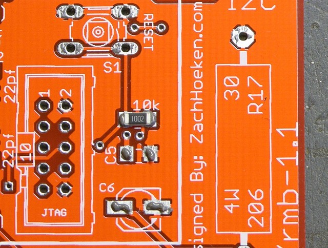
Unlabelled R1 on MakerBot Cupcake motherboard

I did spend a while searching for the placement of R1 on the PC board. I eventually found it through a combination of the process of elimination and checking the schematic. As far as I can tell, the name label didn’t make it anywhere onto the silkscreen — can you spot it?

Storage Storage for Samples Storage

Monday, February 9th, 2009

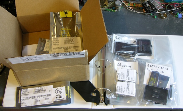
In the past, I’ve tried several techniques for organizing my small quantities of IC samples (and “purchased samples”). I have enough different ones and each needs so little space individually that I don’t really want to dedicate parts bins to them.

IC samples in different containers

I’ve tried putting them in pockets in a three-ring binder, leaving them in the open shipping carton, and leaving them lying around on my workbench in their packages.

None of these have worked particularly well for me.

Mainframe Backup Tapes

At work, we have a large collection of “3490″ mainframe backup tapes, and they’re kept in large racks without the plastic cases the tapes ship in. In the IT environment, large sets of disks and tapes are referred to as “storage;” so the empty plastic cases and the racks the tapes go in are “storage storage,” right?

We had a few empty tape cases left, which were of no use to us and which I took home. We’ve also retired our mainframe and pruned our backup collection, so we have a number of empty racks and rack cases sitting around. It looked like an opportunity to salvage discarded materials and improve my electronic parts storage.

Tape Packages for Electronics Parts

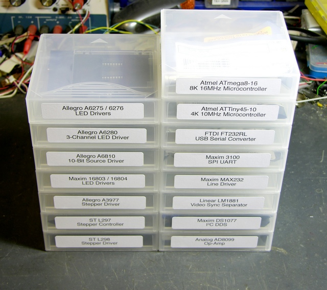
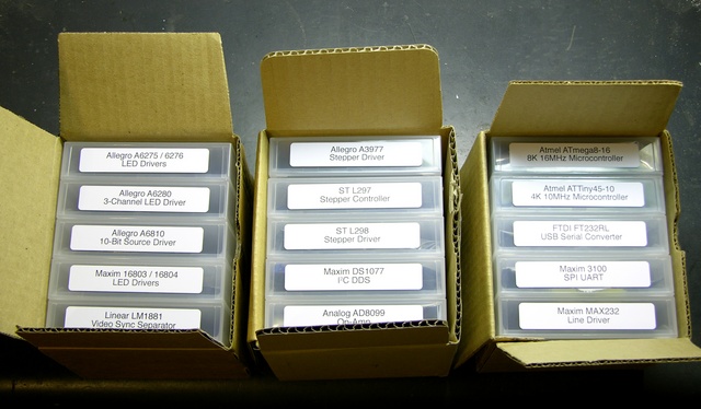
Stacked tape cases with ICs

Last night I put most of my samples into empty tape cases, and it worked quite well. At Wal-Mart I found some Avery labels that are compatible with #5366 (2/3″ x 3 7/16″, called “File Folder — White”), are ultra-opaque, are supported by the label feature in OpenOffice, and fit nicely onto the approximately 1″ x 4.25″ case spines.

Racks (Or Not)

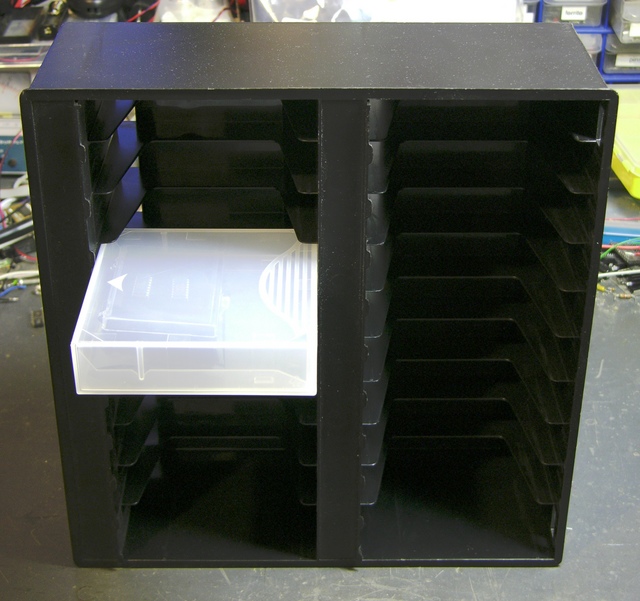
The cases have ridged edges and stack very nicely, but I was hoping to get them into a rack for easy “random access” to individual boxes.

Data tape case doesn't fit into tape storage rack

Unfortunately <grunt>, the racks <grunt shove> weren’t made to hold the cases <curse shove>, just the tapes <growl>, and the cases don’t fit <sigh resignation>.

Boxed tape cases with ICs

I still have some of the boxes that the tapes originally shipped in, but this isn’t necessarily an improvement over just stacking the cases. They’re still sort of “latched” together in the boxes, and it’s almost more difficult to pry a case out of a full box than to balance a stack of cases whilst removing a lower one.

I’ll keep looking — hopefully there’s a rack out there that fits the cases, that someone doesn’t need any more, that I can save from the landfill, and that I get for free. :-)

Motion Sensors for Occupancy Tracking

Friday, January 30th, 2009

This NewScientist article from last spring shows a very cool system of motion sensors for occupancy tracking. The sensors are installed more densely than in typical buildings, so they can detect occupants’ positions fairly precisely within hallways.

The most interesting part of the system for me is the video showing playback of motion through a building — you can clearly see where people were walking, where they ended up, etc.

This seems like a natural fit for a smart house — instead of just watching where there’s motion now, pay attention to where the motion has gone and remember that there must still be someone in that room (even if they’re not moving much now).

$10 Parallax motion sensors + blinders to narrow the cone of coverage + write open-source software for the capture and playback, anyone?

Project Idea: LED Puzzle Ball

Friday, January 30th, 2009

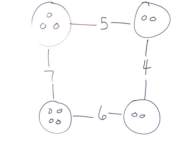
A long time back, I was over at Lawrence’s house and Gail had a number puzzle up on the whiteboard that she was using with her homeschool consortium gradeschool math class.

Number Puzzle

For the students, I think Gail drew the circles with pebbles in them and the younglings had to count the pebbles and write the sums of the nodes into the edges.

For adults, it’s a lot more interesting to start with the numbered edges and fill in the vertices with numbers that make the edge sums work. It’s not hard; it’s just a little bit of a twisty way of thinking.

And you have to keep your vertices balanced enough that you don’t “overflow” an edge. For example, if you started with one pebble in the upper left, then you’d have to have four in the upper right, and then zero in the lower right, and let’s just say that zero pebbles isn’t permitted. Any solvable configuration will have multiple correct answers, but they’re constrained by overflow and underflow of all the edges of the graph.

Puzzle Ball

All of which made me think that this concept could make for an interesting LED puzzle ball. Make a dodecahedron (or a smaller regular polyhedron, or even a larger geodesic shape) with LEDs along the edges and LEDs and buttons (up/down?) at the vertices.

Start it up, the LEDs flash and wink all over the place as the controller randomizes the configuration. Use the buttons to adjust the numbers at the vertices (maybe blue LEDs) so that adjacent vertices add up to the number of LEDs on that edge. As each edge is “solved,” its LEDs change from red to green. Once you have all the edges green, you’re done.

Aesthetics

Seems like it’d be coolest as a “wireframe” polyhedron rather than a solid (or solid surface).

I think I’d prefer SMT LEDs over through-hole. 3mm through-hole if absolutely necessary.

I think I’d like the edge LEDs to be strips of nine that light up fairly symmetrically from the middle out, i.e. something like

----o----              ----o----
---o-o---              ---oo----
--o-o-o--              ---ooo---
-o-o-o-o-          or  --oooo---
o-o-o-o-o         the  --ooooo--
-ooo-ooo-      boring  -oooooo--
-ooooooo-              -ooooooo-
oooo-oooo              oooooooo-
ooooooooo              ooooooooo

I’d like the whole thing to be constructed from PCBs, no separate case. There’ll need to be room for microcontrollers and/or LED drivers. Maybe instead of having the PCBs on the face of the polyhedron, have them edgewise so the PCBs’ outer edges are the edges of the polyhedron. Internally, PCBs could be held together by jumper wires soldered together at the board edges and carrying the signaling bus from one board to another.

Gameplay

I still haven’t decided whether solving the puzzle ball would be fun or merely tedious.

I remember a particular game mode in the old Merlin where you’d press buttons and all the adjacent squares would invert state, with the goal being to get all the lights on or off. I always enjoyed that game, and the way local changes impacted neighboring cells, which impacted strategy for dealing with those neighbors. I would hope that the puzzle ball would be fun in much the same way.

If each edge has nine LEDs (1 – 9) and the game is played with non-modular addition, then the average number of lit LEDs per edge will be 5.5, making the average number of lit LEDs per vertex only 2.75 — that is, on average, only a very few numbers that need to be tried at each vertex. That doesn’t sound like a very interesting game. I could increase the number of LEDs per edge to 20ish, making the average edge sum 10ish, making the average vertex 5ish, which seems okay.

Or should there be ten LEDs per edge and operate in modular arithmetic? Would that make the puzzle too easy, having more correct solutions?

Project Idea: Build a Better Looper

Monday, January 26th, 2009

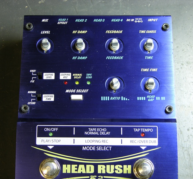
Jeremy and I have been playing with my “new” Akai Headrush E2 looper pedal, which allows you to record an instrument (or whatever) into it; then it plays your mini-recording back for you over and over and over in a loop, and you can play along. You can also overdub, recording more stuff on top of what’s already there and building up a more complex mix in the loop — this is how KT Tunstall does solo performances of “Black Horse and the Cherry Tree”, which are just amazing to watch.

Akai Headrush E2 Delay/Loop controller, cleaned

However, Jeremy and I both have some issues with the feature set and the user interface of the Akai, and we’re thinking about what it would take to build a better looper — or at least, one more suited to our desires.

Feature Wishlist

Here’s what we want:

  • At least 60 seconds of loop time, which would be enough to play 12-bar blues at a fairly slow tempo. The Akai’s 17.8 seconds in low-fi mode is enough for KT to do two measures of rhythm and backing vocals, but not enough to record a full chord sequence.
  • Tap a Record footswitch to begin recording, tap again to end the recording and start looping. It doesn’t absolutely have to be the same switch; but some loopers out there use a potentiometer to set loop duration. We want duration to be determined by the duration of the phrase we played, as it is with the Akai.
  • Independently-addressable tracks or channels. The Akai lets you discard all of your mix except your very first pass and rebuild from there. We want to have (say) eight tracks/channels in the loop mix, each with a footswitch and red/green LED. Tap Record and the next unused channel winks green and records. Tap any channel’s footswitch to put it in (green LED) or out (red LED) of the mix. Not-yet-used channels are dark.
  • Independently rerecordable channels. To rerecord a channel, tap it out of the mix and immediately tap the Rerecord footswitch (which is separate from Record and a little further back or off to the side). That channel winks green and rerecords. Various loopers have varying levels of undo or redub, but none (that I’ve found) let you do this.
  • Ideally have stereo recording so I can loop with the full stereo chorus effect of my analog synths.

There’s room to negotiate on the exact UI, but that should convey the feature set we’re after.

How to Build It?

John suggested using an AudioPint and Pd, and I think I may prototype this with an Arduino to run the control panel and Pd on a laptop to do the audio. But ultimately I’d like to build at least two of these in nice stage-ready stompable enclosures, and I really don’t feel like using a general-purpose OS, for a number of reasons.

It seems to me that this might be a good project for a DSP or an FPGA, but I don’t know enough to make a choice. Any suggestions? (I know I don’t need the full power of a DSP.)

What I’d love to find in one IC would be:

  • Dual 16-bit ADC and DAC capable of 44.1kHz
  • Address and data buses capable of addressing enough external RAM for the audio (say about 1G for stereo * 16 bits * 44100 samples/second * 60 seconds * 8 channels) without my having to worry about DRAM refresh circuitry
  • A processor that I can program for the very simple, core task of summing/averaging samples from the active channels to feed to the DAC
  • ~32 I/O pins to manage the control panel, and/or I2C or SPI to use offboard I/O chips
  • Ideally a USB interface for uploading samples to a computer, but this would be an extremely low priority

Does such a thing exist? Is that necessarily an FPGA? Can I get a development environment for < $500 and a chip for < $30?

(more…)

X-Ray Control Panel???

Sunday, November 16th, 2008

One of the electricians at work gave me a bunch of circuit boards from decommissioned equipment this week. It’s usually elevator stuff, so I hadn’t paid much attention to it other than to note the pretty colored wires.
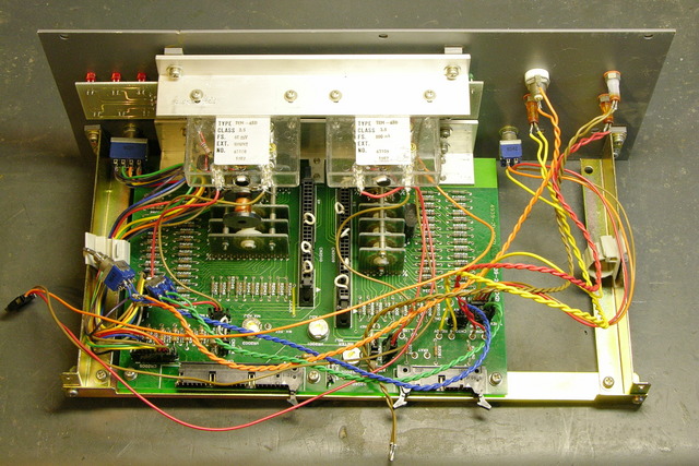
XG controller panel, rear

The I was taking it out of my trunk to put into a “process later” pile when I noticed the front.
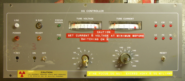
XG controller panel, front

“X-Ray.” 60kV tube voltage. “Fine focus.” Whaaaa???

Combined with the way all the front-panel switches and knobs are bent and broken off, I’m guessing this was in one of the laboratories, some unfortunate researcher accidentally stepped in front of the beam and mutated into a creature with superhuman strength, and in the resulting chaos demolished the equipment. Since it was destroyed, now I have it. Cool!

I went ahead and disassembled it tonight. Here’s a different view of the meters:
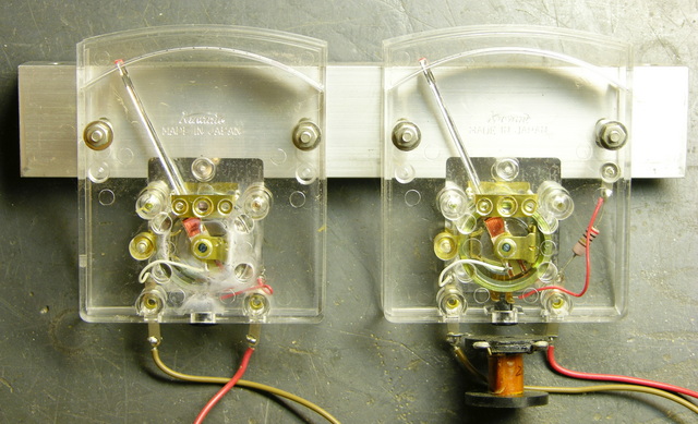
Edge-style panel meters

And there’s a big pile of connectors, resistors, and lovely wires on my workbench.

Cool Rotary Switches

Here are the two rotary switch assemblies. Their knobs were broken off and their shafts bent, so they’re not working terribly well, but I’ve improved them a little.
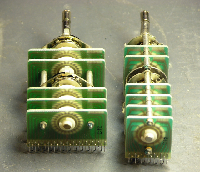
Rotary multi-position switches

They have circuit boards that are ganged together, with the inner shaft turning the back set of switches (of course) and the outer shaft turning the front set.
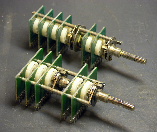
Rotary multi-position switches

The mechanics of the assemblies are fairly intricate. You can click the picture (as always) for the full-resolution version if you want to follow along.
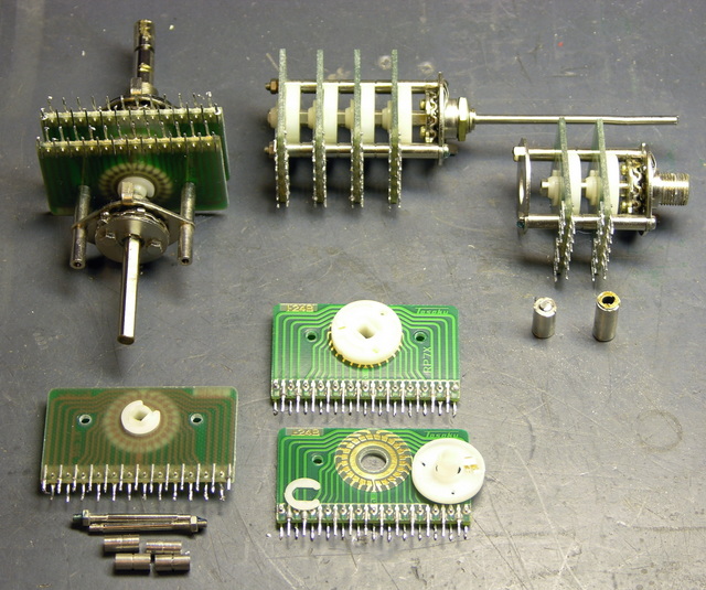
Rotary multi-position switches, partially disassembled

Clockwise from the bottom:

Every switch position is a separate trace on the PCBs, with 24 positions on the wide assembly, 12 positions on the rear part of the narrow assembly, and two sets of 5 positions on the front part of the narrow assembly. A wiper on the plastic rotor connects the PCB’s inner ring trace to each outer pad in turn.

In the upper left, you can see how the limits of rotation are set by two discs with tabs sticking out, which bolt onto the head end of the (sub-)shaft. The discs’ tabs stop against a rear-pointing tab on the head-end mounting plate, which is on the underside in this picture.

Shown at the top, the rear portion of the narrow assembly is still in good condition. It was pretty gummed up, but a few sprays of silicone lubricant got it turning nicely. The PCBs are mounted on a set of multiple threaded rods, threaded spacers, and unthreaded spacers. The rotor’s detent action is provided by the wavy disc on the back side of the mounting plate, a ball bearing sitting in a hole in the plate, and a leaf spring on the front side of the plate.

In the upper right, the front portion of the narrow assembly is okay, but the outer shaft that used to rotate it was sheared off at the base (shown immediately below it).

I had to saw the front knob off the narrow assembly’s shaft to get the assembly apart and make part of it usable. You can see that the kob appears to have been threaded onto the end of the shaft; but with a vise and a pliers, I was unable to turn it loose. The shaft had been pretty badly bent anyway, so I have no hard feelings about having to saw it off.

Idea for Rotary Switches

So I’ve actually been looking for rotary switches like this, and thinking of trying to make some myself. This unfortunately is not the form factor I need, but it shows the idea is sound.

The high school robotics team has strict rules they have to play by, and one of them is that the joysticks used to control the robots in non-autonomous mode must work like PC joysticks (I think the PIC that runs their control panel is charging and timing an RC circuit to determine the joystick position) and cannot have any supplemental power.

This wouldn’t matter, except that the linearity of the joysticks they have is poor; and with (apparently) only 8-bit sampling, there’s not as much they can do programmatically to correct the linearity as they’d like. So it takes a bit of programming effort to eliminate drift when the stick is physically centered; and then when they start to move the stick, the robot lurches into action with not much fine control over low speeds, and at high speeds is pretty much just maxed out.

Of course I assume if it were my robot, I could correct most of that in programming. :-) Still, that’s a lot to ask of high-school kids who are already making amazing engineering accomplishments on a very tight timeline.

So Ron (of the fundraising concert, and father of the team captain) would like to figure out how to build a new joystick that abides by the letter and spirit of the rules but gives finer control over low speeds and has really significant jumps up to maximum speed only when you floor it. Obviously he wants pots with an S curve response (log taper in both directions from center), and he hasn’t been able to find that commercially, at least not that he could retrofit into a joystick.

His idea was to do it discretely — come up with some sort of switching action, then connect that to a resistor ladder. He could play with the resistor ladder to his heart’s content until he got something that “felt” right for the application — make it pluggable and let the kids swap resistors until they got a response curve they liked. And he wasn’t too worried about the robot lurching as the joystick went from step to step on the ladder — he feels that relatively few values would suffice.

If these 24-position rotary switches could fit into a joystick’s gimbal assembly, they’d be fantastic for that! Reserve the middle 3-4 positions for a broad center band to eliminate home-position drift, then have ten more positions in each direction for different speeds.

Except I’m pretty sure the gimbal assembly has little 3/4″-diameter pots right there on it, and these big PCB things just wouldn’t work. Feh.

I thought about etching my own PCBs to replace the wafers inside a couple of sacrificial pots, but I hadn’t figured out quite how to route all the wires out.

Open to suggestions here.
Project Idea: Clock with Sliding Hands

Tuesday, September 23rd, 2008

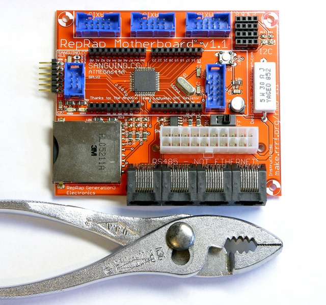
I saw this clock in a catalog last night:

I like 24-hour clocks; and I’m a computer geek, so I use 24-hour time for its unambiguity. And I like the visuals of this clock — but it’s functionally useless and/or made for idiots, as the 24-hour-ness of it is strictly cosmetic. It gives you no idea whatsoever whether it’s currently 07:00 or 19:00; it just has both numbers painted on, and the hour hand will point in the general direction of both.

How ’bout a clock with a face like this — numbers spiralling inward — and an hour hand that slides back and forth end to end across its axis as it turns, so that the end of the hour hand is always touching the marking for the correct hour? At 07:00, the hour hand is still slid most of the way to the outside of the clock and its end touches the 07; at 19:00, the hour hand has withdrawn further across the center of the clock and its end touches the 19.

Of course it’d need to be done with gears; I’m not talking about an LED or LCD clock.

LED Calculator with Rotary Quadrature Encoder for Target System Voltage Selection

Sunday, July 6th, 2008

LED calculator with rotary encoder for target supply voltage

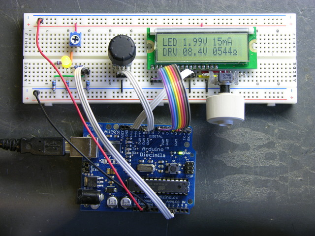
I’m still working on the LED calculator (original idea and most recent work) — I’ve finally got ’round to adding a rotary encoder to set the target system voltage. Now you can turn the potentiometer to set the LED brightness, turn the rotary encoder to set what voltage will be used in the ultimate LED circuit, and read the LED voltage, current, and current-limiting resistor values off the screen.

I also found the Ω in my LCD’s character matrix, so I tidied up the display a little.

And most significantly, I wrote an Arduino library for reading (multiple) quadrature encoders. The simple approach of polling them inside loop() was causing me to lose a lot of steps from the encoders; and the code to read them using hardware external interrupts (lower on the same page) only works on digital pins 2 and 3, so only supports one encoder if both pins are wired to interrupts for the highest resolution, or two if interrupting on a single pin and polling the other.

My Quadrature library uses the TIMER2 overflow interrupt service routine to poll multiple encoders rapidly and track the results, supporting as many encoders as you have room for on the digital pins. It also encapsulates all the dirty work into the library code, so using it is as simple as

#include "Quadrature.h"

Quadrature myencoder1(9, 10);  //  Connected to pins 9 and 10

loop() {
  x = myencoder1.position();
}

It still has some rough edges and it’s by no means perfect (more on that below), but it sure makes it easy to use rotary quadrature encoders. It’s available on a new Downloads page for anyone interested.

(more…)