Archive for the ‘LED Puck’ Category

ABS Puck Case Prototype

Saturday, March 14th, 2009

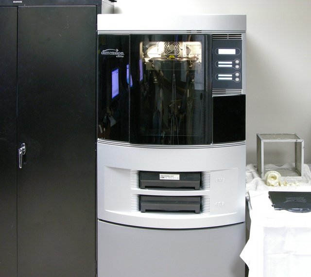
Dimension Elite 3D Printer

A while back, I had contacted Brian Brown, associate director of the CAD/CAM lab at the university’s National Institute for Aviation Research and a great colleague of mine, to ask whether they had any rapid-prototyping machines that could churn out a prototype LED puck case in a transparent or translucent material.

Dimension Elite 3D printer

They didn’t at the time, but Brian contacted me last week to say that they had a new Dimension Elite 3D printer and they’d be happy to print me a case while they were ramping up on learning to use it. I emailed over an STL export of my Blender model, Brian put his student Jonas Fink to work, and the next day I went over to take pictures of the machine in operation.

As it turns out, the “natural” colored ABS plastic isn’t translucent enough to use as a functional test enclosure, but it makes a great physical prototype. More on that in a bit.

How It Builds

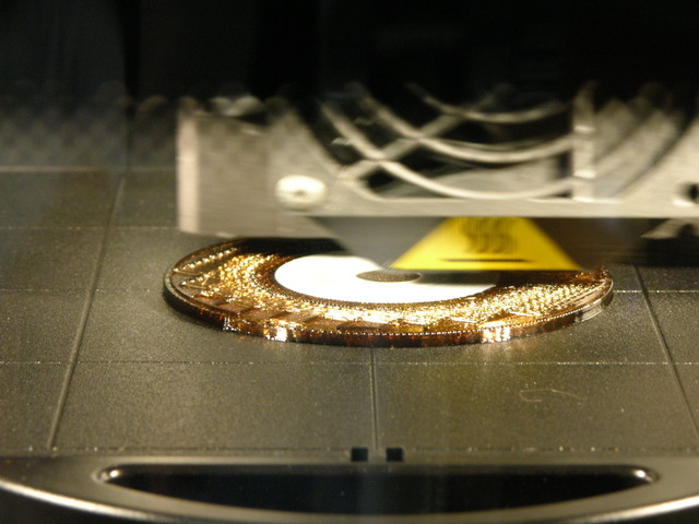
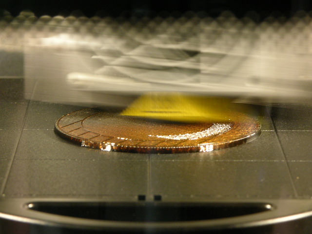
Dimension Elite 3D printer building support structure

The machine extrudes a tiny “string” of ABS plastic onto a removable tray. It first lays down a brown support structure to hold up any overhanging areas, and the support material is a soluble form of ABS that’s later removed in a detergent bath. The extrusion head moves around one entire horizontal plane, “drawing” in all the material that appears there, then lowers the tray slightly and draws in the next layer.

Dimension Elite 3D printer beginning to build puck case

Once the support structure is in place, the machine extrudes plastic for the actual model — still continuing to build support structure for higher overhangs. My puck case was being built upside-down (as a bowl instead of a dome); so here you can see the puck material in the center as the machine works its way out from the low center of the bowl up the curved edges.

Breaking It Loose

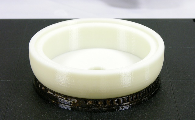
Completed ABS puck case prototype, front view

The build ran past the end of the work day, so I went back the next morning to see the completed prototype, still attached to the tray. If you look closely, you can see the layers of “threads” that were used to built up the model, with the support structure underneath.

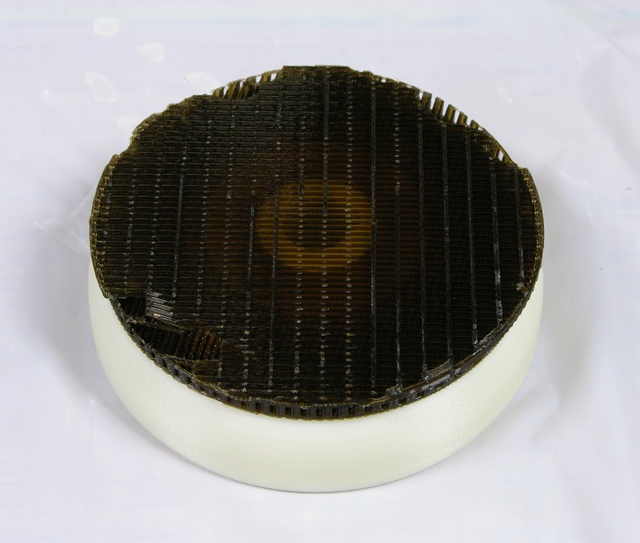
Completed ABS puck case prototype, support structure upper front

After breaking the model free of the tray, the sparse honeycomb-like nature of the support structure is even more evident. The light ring in the middle is the bottom-most layer of model plastic surrounding the hole for the pushbutton switch.

Although the suggested means of removing the support structure were to put the whole piece into the cleaning tank for a few hours and let it dissolve, I was curious how sturdy the support was and found that I could actually pry and crack it loose of my model using my pocketknife. I managed to get the whole thing cleaned off without using the tank or cutting off a finger.

The Result

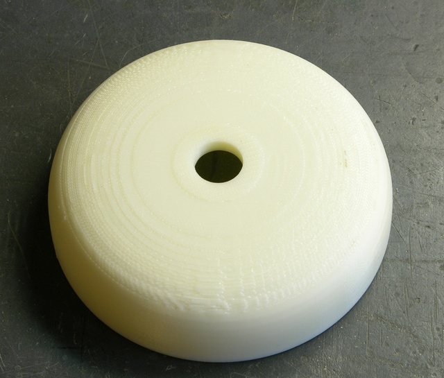
ABS puck case prototype

The finished prototype is rougher on the top than I expected — this machine (at least as programmed for this run) doesn’t seem to build a smooth finishing surface on the support structure before beginning to build the model, so the first surface of the model has the jaggies. You can easily see the contour become smoother around the knee of the curve, where it stopped building support because the slope of the overhang could be built directly.

I’m guessing if the machine did lay down a smooth layer of support before starting the actual model, I wouldn’t have been able to break off the support as easily, and I would have had to use the cleaning tank. That still seems like a good tradeoff for a smoother model.

As to the utility of having an opaque prototype of a clear case — pretty darn high. One of my puck design goals is that its size and shape make it comfortable to carry with me all the time, preferably in a back pocket. I’ve been doing exactly that since Tuesday with this ABS case, and I gotta tell you, it’ll work great. No complaints yet, sitting on it all day, driving, you name it.

Fitting Batteries

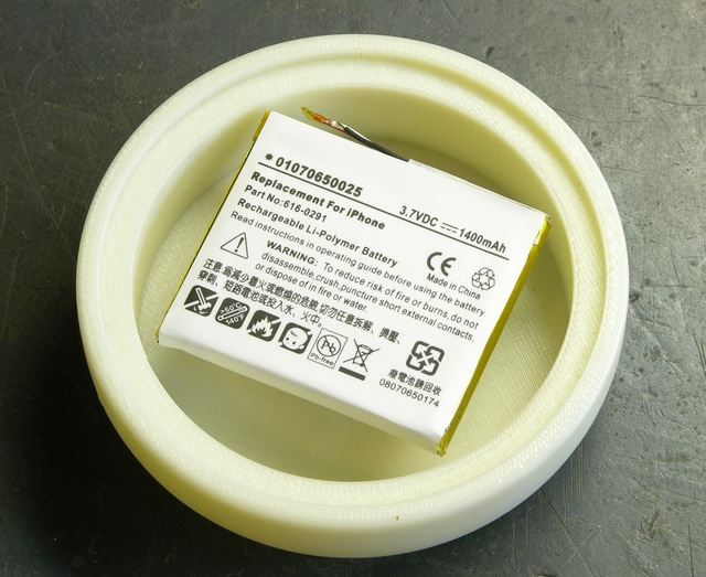
ABS puck case prototype with iPhone Li-Po battery

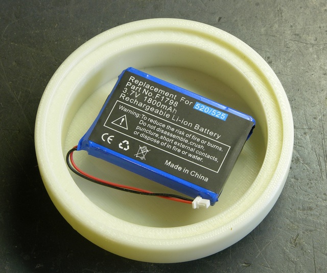
A little over a year ago, I had been really pleased with the service I got from eBay seller Digital Power Pro on a replacement battery for my Visor Prism, and contacted them to ask whether they sold any Li-Ion or Li-Po batteries with the mAh rating I was looking for and of a size that would fit inside my puck case. They were entertained by the question, and recommended an iPhone replacement battery and an HP Jornada battery.

ABS puck case prototype with HP Jornado Li-ion battery

They both fit nicely into the recess, with the iPhone battery being a little slimmer in case I run out of room.

Next step: milled acrylic case.

Puck is Stale But Not Forgotten

Friday, October 3rd, 2008

Wednesday over lunch, my brother sent me to Lustercraft Plastics to pick up a window well cover to replace one that got broken at a customer’s house.

And wow, their showroom is droolicious. Lots of sample tiles of different types, transclucencies, colors, and textures of plastic. Plastic dowels so dense they might as well have been cudgels. Flipchart-style collections of crazy bright colors of what felt like UHMW plastics. Really cool stuff. I need to go back and take my camera (with their permission) to get pictures of all the goodies.

Near the counter, they had a few trinkets, including a truncated cube (hm, maybe actually a rhombicuboctahedron) made of a clear plastic that still had a few deep milling gouges but was otherwise very well polished. I was impressed with how well it had shined up after cutting, so I asked what kind of plastic it was — and it turns out it was acrylic, aka plexiglas.

And they have cutoff scraps in the back, sold by the pound.

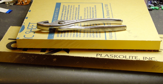
18mm and 25mm acrylic scraps

These 18mm and 25mm scraps of clear acrylic (underneath the paper covers) look to be good for milling puck cases, don’tcha think?

The puck project got stalled because I’m fussing over power issues — doing proper USB negotiation for 500mA (everyone assumes you can just grab as much as you want, but it’s a violation to take more than 100mA without asking), doing proper Li-Ion charge management (don’t want to cause the battery to vent with flame), and doing full-fledged power management (mediating among an external power source, a battery that can source current when needed or sink current when charging, and an LED load that has the potential to sometimes be higher than the 500mA max USB current).

But I have samples of parts for all those things, and the project isn’t dead yet. It’s just pining for the fjords.

Parallax Motion Sensor from Radio Shack

Saturday, January 5th, 2008

The back cover of Servo Magazine is always an ad from Parallax, and the December issue featured several sensors that will now be distributed through Radio Shack, including a motion sensor for $10.

John and I are getting ready for this spring’s Technology: Art and Sound by Design class; and although I think John will be doing most of the teaching this year, I’m always on the lookout for sensors that would be good for students’ interactive sculptures.

Jason at work suggested that the LED puck could have a motion-sensing mode, to serve as a sort of intrusion alarm.

When two separate events occur simultaneously pertaining to the same object of inquiry, we must always pay strict attention. Or, ah, three events.
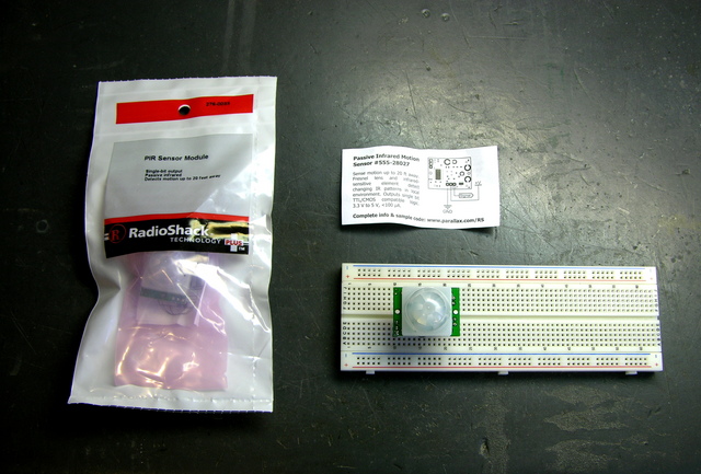
Two Parallax / Radio Shack motion sensor kits

I picked up a couple of the sensors last week to try out. The clerk said when they got them, he had thought they’d never sell any. Why am I always the guy buying the weird stuff?

How Motion Sensors Work

The heart of common motion detectors is a pyroelectric sensor, which is essentially a FET with a window in the case opening onto an infrared-sensitive gate. Changes in the level of IR light with a wavelength corresponding to body heat cause changes in the drain-source resistance, which the circuit monitors.
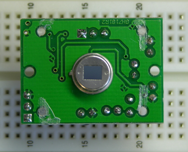
Parallax pyroelectric sensor

The real trick is that the sensor is then placed behind a multifaceted lens that (loosely speaking) “chops up” the view of the world into smaller cones of heightened visibility and intervening areas of lessened visibility. Think of a stage polka-dotted with multiple spotlights, only actually seeing that way rather than merely illuminating that way.

A body moving from an area of reduced visibility into an area of increased visibility causes a rapid change in the amount of IR (body heat) shining on the sensor, hence a rapid change in its drain-source resistance. The motion detector circuit watches for these rapid changes, and when detected, triggers the alarm. This is why Robert Redford has to move slowly while retrieving the MacGuffin from Cosmo’s office in Sneakers.

A brief note about the multifaceted lens: It is usually a Fresnel lens, but being a Fresnel lens is a red herring. That simply makes the lens thin and easy to mold out of plastic; it is really the multifaceted nature of the lens that’s important. Closer examination of a motion sensor lens easily reveals that it comprises multiple adjacent Fresnel lenses.

The Fresnel dome of this sensor, by the way, is too large to fit into the LED puck (as, most likely, is the PCB). However, it’s not out of the question to purchase a separate PIR element and mill a multifaceted lens pattern into the puck enclosure above it. It would be an interesting challenge, perhaps for a later version.

The Parallax Sensor

The sensor comes with an absolutely minimal connection diagram, and refers to the Parallax web site for full documentation. The module has a three-pin connector (bottom) for ground/V+/output, and a two-position jumper (upper left) for retriggering mode.
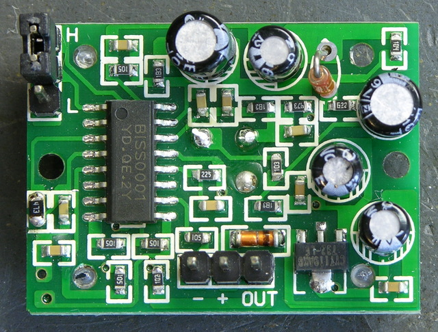
Parallax motion sensor, component side

The power/output header is annoyingly the same height as the other components on the back side of the board, so the sensor cannot be plugged directly into a breadboard for prototyping; it requires an extension. Parallax recommends a servo extension cable; I soldered a three-pin header to a three-pin header socket to make a rigid extension for breadboarding.

The module’s output is active-high. The Parallax documentation indicates that the jumper selects retriggering mode. With the jumper in the L position, the module triggers the output upon detecting motion and then goes low again. With the jumper in the H position, the module is supposed to keep the output high as long as motion continues, but mine does not.

The datasheet indicates that the module needs a “warmup” period of about a minute, during which time it’s adapting to ambient conditions and may trigger randomly. My experience was similar, so anyone using this module needs to be prepared to accept random triggering for a while after startup.

The package and datasheet indicate a detection range of about 20′. I didn’t have room to test this, but I’m willing to believe it until I learn otherwise. Apart from the minor annoyances above, the sensor really is very easy to use, particularly for our class. It seems quite responsive to motion, and certainly responsive enough to pick up gallery visitors not specifically trying to sneak up on it. Output is a very clean 5V, so it’ll be easy for students to interface to the Arduino.

Sensitivity is fixed. It’d be nice to have a trim pot to adjust sensitivity/range, particularly for use in interactive sculpture projects. A Halloween prop-maker going by the name “Scary Terry” has written a nice review of the motion sensor, and includes pictures of mounting it inside PVC pipe to control its angle of sensitivity. I guess with care, the sensor could be angled toward the ground in such a way that it would be triggered only when feet entered a designated area.

Hacking the Sensor

I suspect that most students using this sensor either would trigger a long sequence of actions when motion is first detected, or would like to get a continuous (retriggered) signal the entire time motion is detected. I’m somewhat interested, though, in a much finer-grained notion of “the entire time motion is detected” than that.

By my rough count, the sensor triggers for about two and a half seconds each time it detects motion. It then locks out briefly (didn’t time it — say another couple of seconds?) during which time it’s insensitive before it can detect motion again.

I’d like to be able to get a series of much shorter spikes and much shorter recovery time. I don’t know exactly why; it just seems useful to me.

Let’s go back to that component view:

Parallax motion sensor, component side

The IC doing all the work is a BISS0001. The only datasheet I can find for it is in Chinese, yay, don’t read that, sorry. The chip has a bunch of comparators, some logic, a logic section labelled in Chinese, and two timers labelled in Chinese. It looks like it’s probably made specifically for motion-sensing applications.

Fortunately the pinouts and component values are labelled in English, so I was able to make enough sense of the datasheet to understand how to set the timing constants. From the sample application circuit, pin 2 is obviously the master output; and on the pinouts, pin 2 is labelled VO.

On the timing diagrams, VO goes high for a period labelled TX and low for a period labelled Ti. Just above that, we have the equation TX ≈ 49152R1C1 leaping out at me from a wad of impenetrable Chinese. On the functional diagram, R1 and C1 stack from pin 3 to 4 to ground.
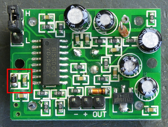
Parallax motion sensor, pulse timing components

Okay! On the PCB, pin 3 goes to a resistor that said “204.” (Ignore the 473 in the picture.) The resistor and the IC’s pin 4 go to a capacitor, which goes to ground. We’re in business!

The resistor is labelled as a 200KΩ, and my meter confirms that. The capacitor is unlabelled; in-circuit, my meter tests it at about 470pF. Doing the math:

49152 R1 C1 = 49152 * 200KΩ * 470pF ≈ 4.6 seconds

Hm, that’s a little off from the 2.6 seconds I was counting, but same order of magnitude. For a capacitor value that small, I’m willing to believe that I’m getting extra capacitance from my meter probes and from measuring it in-circuit. I think we’re in the ballpark.

The easiest way to shorten the on-period (TX) seems to me to be replacing the resistor. To take the period down an order of magnitude, I should use about a 20KΩ resistor. After looking at the SMT resistors on a dead PC motherboard, I found a 473 (47KΩ) and figured it was enough smaller to make my point.

I desoldered it by wrapping a piece of heavier wire around it and heating the wire, like Josh suggested, and it worked great. Then out of laziness and because the new resistor was larger than the existing resistor and might not fit the pads well, I just soldered it on top of the resistor that was already there, in parallel. Makes it a 38KΩ resistor instead of a 47KΩ, so we’re even going in the right direction.

I powered up the motion sensor again, waited a minute for it to settle down, and started timing its response. On-time after sensing motion (TX) is now in the half-second range. The absolute numbers still don’t match what the equation says I should get, but the relative values are right on — a resistor with 1/5 the value reduced TX to 1/5 of its former value.
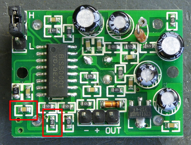
Parallax motion sensor, lockout timing components

Pretty slick! Now I can pick whatever TX I want, be it short or long. I haven’t tried it yet, but the lockout time between motion detection (Ti) is set by R2 and C2 on pins 5 and 6, and they’re easily accessible as well, so I should be able to change that too.

And About that Datasheet . . .

Don’t get me wrong about the Chinese datasheet. Sure I would have been disappointed if I couldn’t read it, but I was actually really pleased that sections of it were in English. I’m aware that people throughout the rest of the world have to learn English in order to do a lot of technical things, and do so with ease and proficiency much greater than that of the few Americans who bother to learn languages other than English.

Bunnie Huang has an interesting blog post that touches in passing on certain types of devices using chips of Chinese manufacture that can’t be found, or can scarcely be found, by searching Google in English:

Just try searching for USB mass storage controller ASICs, or digital picture frame SoCs on Google in English, and then go and open up one of these devices and compare your findings. I bet you’ll find that the chips most frequently used in these popular devices are best searched for in Chinese.

It’s a competitive world out there, and those of us in the west have had it awfully easy for an awfully long time. I know as a mere hobbyist, the technology I use is far behind the leading edge, and I’m not yet impacted in nearly the way of engineers developing new products for market. But the world is changing, no doubt about it, and I hope it’s a while yet before it impacts my ability to tinker.
Merry Christmas to Me!

Friday, January 4th, 2008

When I thought up the LED puck idea, I went shopping for some bright LEDs to put into it. I don’t like the blue+yellow color of “white” LEDs, and I thought it’d be fun to have green illumination, so I found some green LEDs from a Hong Kong [correction: Chinese] eBay seller and bought ‘em. Since I’m pretty sure it costs about the same to ship a package from Hong Kong China if it has a few more items of negligible weight in it, I kind of went crazy and treated myself to an LED assortment.

I won’t mention the specific eBay seller, because I have mixed feelings about them. On the one hand, their prices were very good and their LEDs seem okay. On the other hand, I’m pretty sure it cost them next to nothing extra to ship my whole package than just my first LEDs; but even after requesting and receiving an additional additional shipping discount, I still paid $30 shipping for $35 of LEDs. And on the gripping hand, I paid on December 9 and didn’t receive my package until December 24. It made a nice Christmas present to me, but it made me feel like I was paying shipping by the day instead of by the pound.

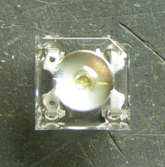
Square 5mm LED

Grumbling aside, the LEDs I was shopping for turned out to be not at all what I was expecting, and probably better in every way. This is because I wasn’t paying enough attention to see that they have four legs (I thought they were two-legged LEDs with a square base), but four legs gives better heat dissipation and allows higher current; and I didn’t realize how squat they are, which makes them fit better into a puck; and I saw that they were 1500 mCd but didn’t realize they had a 120-140° viewing angle, which means they output a whopping 4.7-6.2 lumen each. In contrast, my 10,000 mCd 20° blue LEDs only output .95 lumen.

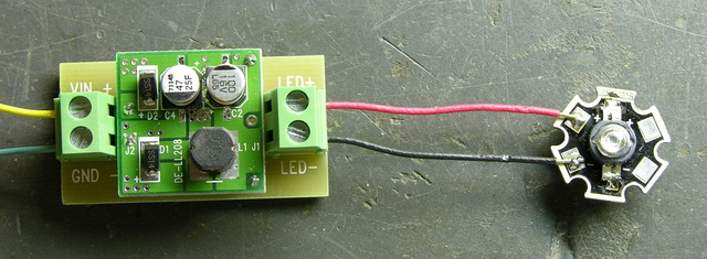
The other stuff I got was a handful of 1W and 3W Luxeon knockoffs, because, y’know, why not; and a constant-current driver board, which I thought would come in handy while testing.

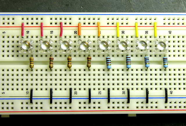
Here are eight of the 5mm LEDs on a breadboard with 100Ω resistors, for about 15mA at 5V or 85mA at 10V (~3V drop). Remember, that’s maybe 5 lumen each or 40 lumen total.

Square 5mm LEDs on breadboard

Let’s see how they fare against the 3W, 70 lumen beast of the apocalypse, wired to the 1W driver without thinking about how that means it’s not running at full power and brightness.

LED driver and 3W green LED

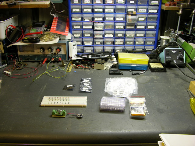
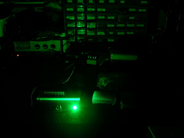
Here’s my desk with about 200W of fluorescent light from the ceiling fixture and the swing-arm lamp.

Desk lit with fluorescent lights

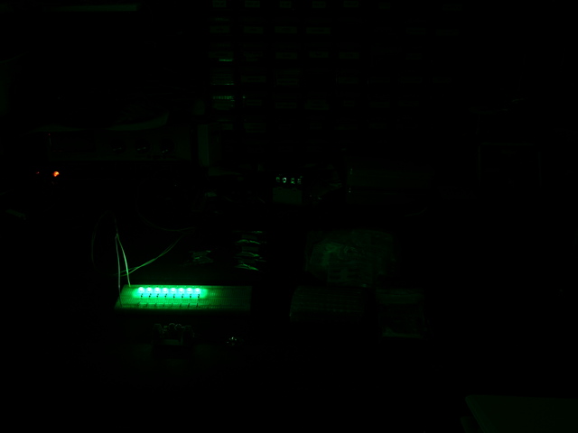
Same scene with the eight 5mm LEDs fed at 10V, and the camera locked to the same aperture and shutter speed:

Eight green LEDs

Same scene with THE BEAST:

3W green LED

Assessment:

The LEDs don’t provide nearly as much illumination as normal room lighting. But then, nobody thought they were going to.

Each set of LEDs does provide enough light to read by, pretty comfortably, even with the light in the same plane as the paper’s surface (i.e. indirect lighting).

According to the camera, half the LEDs for the puck make less light than a single 3W faux-Luxeon driven at 1W. Crap, I should just make a Luxeon throwie and call it a puck. Nah, that’s not really the fun part of the puck idea.

According to my eyes, and my wife’s as well, there’s much less subjective difference in the brightness between the eight 5mm LEDs and the single 3W LED than what the camera appears to show. The math seems to back this up as well (maybe 40 lumen versus some fraction of 70 lumen), so I can’t explain what’s going on in the pictures.

And, oh yeah, LEDs ARE COOL!!!

LED Puck: Blender Modeling

Thursday, January 3rd, 2008

Joel is setting up EMC2 so we can use his CNC machine for milling (DanCAM could mill, but we’d probably have to use DanCAD so we’ve just used the machine for drilling), and I’ve been working on modeling the puck enclosure in Blender.

First, I’d like a better visualization than my crude line drawings; and second, Blender has a plugin to output STL (stereolithography) code, which FreeMill is supposed to be able to convert to g-code, which EMC2 (and everything else in the world) can mill. So at the same time, I get a visual idea of what I’m designing and a CAM file to produce it. Almost like using CAD software. :-)

I am completely new to Blender, which is obvious both by how long it took me to build a satisfactory model and by the amateur appearance of the result. At the end of this post is a plea for education, if anyone wants to teach me how to do it better.

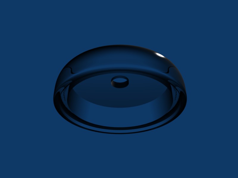
Here’s a view of the draft enclosure from slightly above, rendered translucent (plexi or lexan):

LED puck case modeled in Blender, translucent, from above

The hole through the top will host a waterproofed plunger for the pushbutton switch, but the plunger is absent because I’m only drawing the case for now.

Same draft viewed from below:

LED puck case modeled in Blender, translucent, from below

There’s a shallow recess for mounting a plate to seal the bottom, then a deeper recess for the PCB and battery.

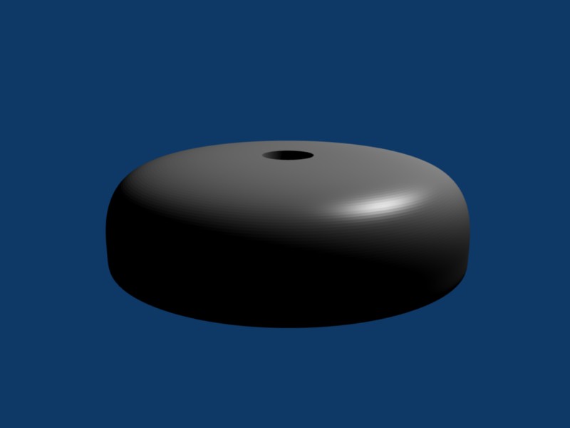
Same case in Blender’s default material (scrith?):

LED puck case modeled in Blender, default material, from above

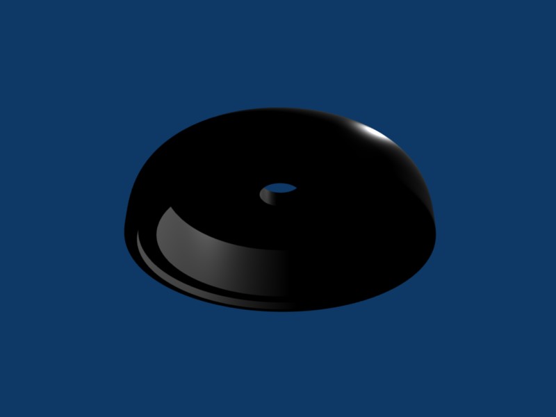
And from below, which is way too dark but may show a little more detail of the nested recesses:

LED puck case modeled in Blender, default material, from below

Below, detailed information on how I made this in Blender, for anyone interested, or willing to offer advice.

(more…)

LED Puck: Tilt Prototype

Thursday, December 27th, 2007

My wife isn’t interested in electronics. She doesn’t do electronics, she doesn’t understand electronics, and she really doesn’t want to hear me ramble on at length about electronics. (I say this all in a very good-natured way, of course. Identical interests were not a prerequisite for our marriage.)

So when my wife asks my why I keep soldering chips onto boards in the wrong direction, I know I have a problem.

Oh, and the ADXL202 is a hardy little sucker.

Prototype Puck I/O Board

Over the weekend, I laid out and built a prototype of the I/O for the puck — just the LEDs, their driver, an accelerometer chip, and a pushbutton. I expect to use the Freeduino circuit for the microcontroller and will still need to add it to the board (as well as battery-charging circuit and all that other good stuff); but I wanted to get started programming the actual LEDs and tilt system.

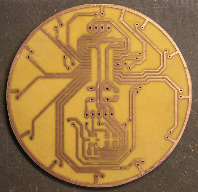
LED puck I/O prototype PCB, cleaned and cut

I laid out the board in EAGLE; and believe me, it’s a bit of a challenge routing nice curves as traces. The V+ circle around the edge wasn’t too bad; but I wanted to route the LED drive traces as concentric arcs and just couldn’t find a way to do it.

I had a few SMT A6276 LED driver chips around, so I was able to make most of the board SMT already. The A6276 will want to be on the underside of the board (shown here) so its pins are in the same order as the LEDs it drives. I’m not sure where the other chips should be, but it was easy to make a single-sided board for this prototype.

I worried that I was packing the traces too closely together; but they came out well enough (iron-on toner transfer), I think I could have made them smaller. And having to run to headers to go off-board to the Arduino complicated the routing; if the microcontroller were on the other side of the board, each of those signals could have gone through on a via wherever it was convenient rather than having to converge to the two headers at the top and center.

Tinnit

I tried plating the board with Tinnit, because I had such good results last time — that board was incredibly easy to solder. Alas, five-month-old eighteen-year-old Tinnit apparently doesn’t work very well. After forty minutes at 110°F with no plating appearing on my traces at all, I gave up, washed the board clean, and dumped the rest of the Tinnit.

I still think it’s great stuff and I intend to use it again. I just need to be sure I’ll be making enough boards for it to be worthwhile.

I did learn something else, though. After cleaning the board, it sat out for a few hours, and I noticed that it was already oxidizing — the copper was considerably less shiny than when it was fresh. Before soldering, I polished it with wet 600-grit sandpaper, and it took solder beautifully — completely unlike untinned boards I’m used to soldering.

Lesson: If a copper board has been exposed to air for even a few hours, polish it with wet, fine sandpaper before soldering.

Assembly

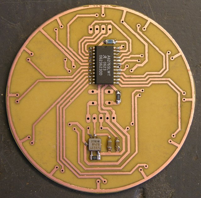
I soldered on all the SMT components first. I was pleased that I was actually able to find all the resistors and capacitors I needed in my salvage bin. I’ve desoldered a number of SMT boards (heat with heat gun, then bang on the bench vise and the components come flying off; or pluck them off with tweezers for a more orderly approach), and I think these came from a dead Cabletron hub.

LED puck I/O prototype, SMT components soldered

The resistors were all labeled, so they were easy to search for the right values (if you call picking through a bag of grains of rice easy). The capacitors were a bit more challenging — they were completely unlabelled, so I had to dump them out on the workbench and use the meter (tweezer-style) to find the values I needed.

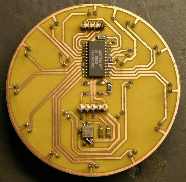
LED puck I/O prototype, copper side

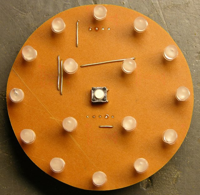
I placed all the LEDs with their cathodes facing clockwise (as viewed from the top) for simplicity — so I wouldn’t have to think about which way each one goes. Although parts of the puck are obviously asymmetric, I prefer to think of the puck as a whole having at least rotational symmetry, and I wanted the LED orientation to reflect that as well.

LED puck I/O prototype, LED side

The jumper wires are a bit scabby, particularly the one running halfway across the board at an odd angle; but again, they’re at least partly due to routing challenges with not yet having the microcontroller on board, as I mentioned earlier.

I should stop to add that laying out an SMT board is really refreshing, in that you can fill both sides of the board with components and traces, and not worry about through-holes impacting the routing on the other side of the board. As long as you don’t need to hop to the other side and back to cross one trace over another, each side can be completely independent of the other.

That’s not illustrated well by my single-sided SMT board; but I mention it because I’m really looking forward to laying out the microcontroller (probably on the top side) and cleaning up some of these traces and jumpers.

Two Mistakes on the Accelerometer

First: absent-mindedly running the resistor that sets the PWM output period to the self-test pin by mistake. Second: soldering the accelerometer to the board 180° from its proper orientation.

When I first powered up the board, I was most interested in testing the LED driver, since I had already tested the accelerometer on the breadboard. The lights didn’t come up (I had forgotten to manipulate the output enable line in my program), but I also smelled hot electronics. I fixed the program, the LEDs worked, the accelerometer didn’t, and I realized my mistake.

On the EAGLE PCB layout, I had a marking for the accelerometer orientation, of course. But the marking was on the silkscreen layer, and I didn’t make a silkscreen layer when I etched the board at home. Then because the components are on the bottom side, I got myself confused about which end of the accelerometer was which.

Lesson: Copy IC orientation markings to the copper layer for homebrew boards.

Rework

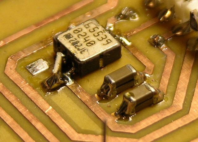
Last night I waved my soldering wand and cast a spell of devious reparo on the accelerometer chip; but apparently it backfired, because it ended up looking like this.

Closeup of LCC and stacked SMT capacitors

I actually used solder wick to remove the errant PWM period resistor — it did a nice job of sucking up solder, heating both ends at the same time, and then scooting the resistor off its pads so it wouldn’t stick back down when the solder cooled.

I used solder wick to suck up all the solder I could from around the accelerometer; but I didn’t have a way to heat the whole thing at once, so I couldn’t scoot it away. I need a hot-air pencil and looked at several DIY designs, but didn’t want to take the time out to build one. There was little enough solder left, I was able to twist the chip off the board with a pair of pliers.

I lost a couple of pads in the process; but when I soldered it back down, one was NC and the other I was able to bridge with solder. Then I needed to move one of the resistor traces from the left pin to the middle . . . and the easiest way to do it was to solder one end of the resistor directly to the chip.

Yes, I’ll fix it right in EAGLE for the next board.

BTW, notice the stacked SMT capacitors on the right. I couldn’t find anything in the .1uF – .2uF range in my bag, so I paralleled a couple of 75nF. Nasty!!! :-)

Proto-Puck

The upshot of all this, if I can finally get to the point, is that I have a working proto-puck.

Arduino and puck

I have ribbon cables connecting it to the Arduino for power, LED output, and tilt input. The LED driver works perfectly, and (miraculously) the accelerometer works now that I’ve reoriented it. And that means I’ve been able to start writing code.

This isn’t much yet — it only detects whether the tilt is inner or outer, and which quadrant it’s in — but I think it gives a flavor of things to come.

LED Puck: Tilt Video

Friday, December 21st, 2007

Many thanks to John Harrison for showing me how easy iMovie is to use.

YouTube must by default pick the middle frame of the whole video for the thumbnail screen? I’ve updated it to use a different frame, but they say it can take six hours to take effect. Meanwhile, here’s a great video apparently about hysteresis!

YouTube has synced my change for which frame gets used for the video still, so the joke about the hysteresis video doesn’t work any more.

LED Puck: Need an Inexpensive Accelerometer

Wednesday, December 19th, 2007

I thought I’d seen an accelerometer chip recently that retailed for $3-5, but the cheapest I can find on Digi-Key is $7-9. I’m really worried about the puck price climbing out of control. Anyone know of cheap accelerometers?

LED Puck: Concept Drawing

Tuesday, December 18th, 2007

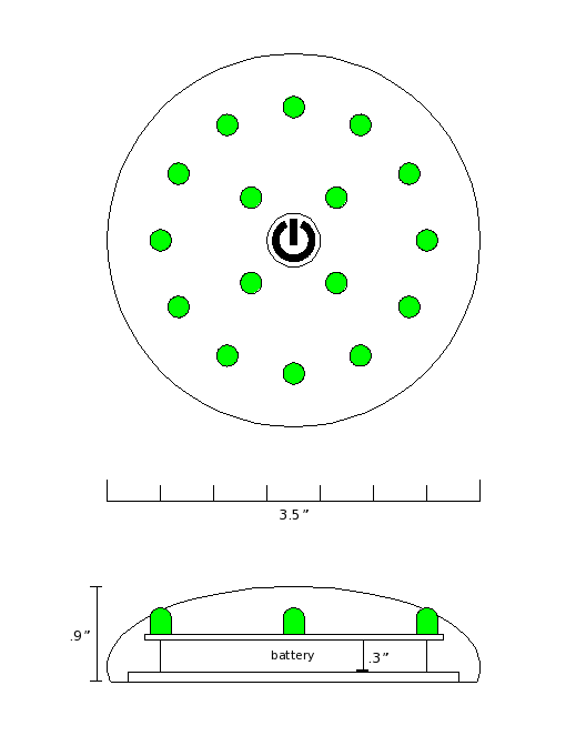
LED puck concept drawing

Hm.

(Click above for unsquished version. Well, unsquished graphic. The design is still too squished.)

LED Puck: Parts List Draft

Monday, December 17th, 2007

If I don’t make a list of everything I need to get, I’ll end up waiting on a parts order before I can finish a prototype, or worse, leaving something off the design entirely.

ICs:

  • Atmel Atmega8 or Atmega168 for Arduino/Freeduino
  • USB interface chip?
    maybe only if USB is going to be externally accessible; could use LadyAda’s FTDI USB cable if willing to get inside to reprogram
  • voltage boost / regulator
  • battery charging controller
    maybe LM3622 used in the WaveBubble
  • Allegro A6276 16-bit LED driver
  • digital resistor for LED current reference and dimming?
    or could PWM A6276′s enable line — I probably like the PWM idea better
  • accelerometer / tilt sensor
    sample the cheapest one I can find and make sure it’ll work — probably a thermal
  • Dallas RTC
  • temperature-compensated crystal oscillator for RTC
  • *PROM for fonts for POV mode?
  • EEPROM for saving configs and POV text?
  • LM34 Fahrenheit temperature sensor?

Other:

  • ultrabright 5mm LEDs with > 30° viewing angle (15° half-angle) and prefer > 10,000 mcd
  • very slim high-energy-density battery
    16 LEDs * 25mA/LED = 400mA, so well over 400mAh for an hour of runtime at full brightness
  • coin cell and holder for RTC chip and oscillator
  • watertight mini-USB connector for tethered charging and reprogramming???
  • photoresistor or LED for light detection (maybe several around the edge?)

I’ve kind of dropped connectors for remote wired control, and wireless for a keyfob control. How much do those matter?