Archive for the ‘Inside’ Category

Fixing a Kids’ Educational Toy

Sunday, January 13th, 2008

Alphabet training toy

A while back, my wife got this alphabet-training toy for one of our nephews. When they opened it and tried it, it “didn’t work and the batteries got hot.” Sounded like a short to me, so I figured I’d take a look.

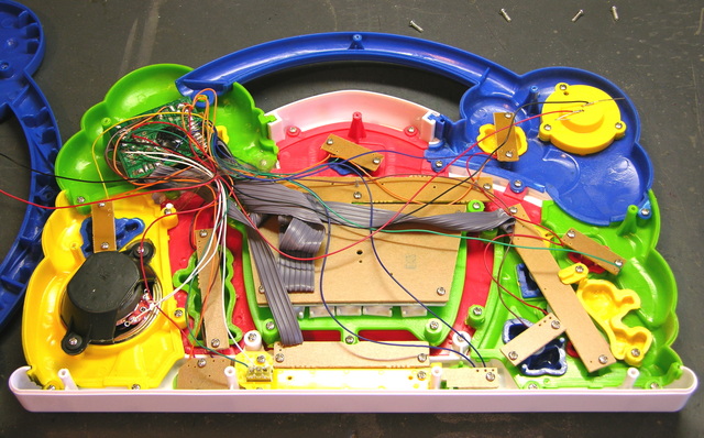
Alphabet training toy, interior

The inside was interesting — I wasn’t expecting a bunch of little pushbutton circuit boards and a ton of fly wires (bundled together with cellophane tape), but I guess it makes sense. In China skilled labor is cheaper than automation, so a bunch of little boards with hand-soldered wires probably cost less than one big board made by a machine.

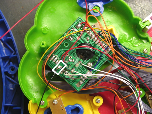
Alphabet training toy main circuit board

I put my meter across the terminals of the (empty) battery compartment and measured 0Ω — a dead short. I visually inspected every connection on the main PCB, assuming I’d find a solder bridge, but I didn’t. I desoldered the battery and power LED ground wires from the PCB (outlined in the white rectangle) so I could start isolating the short, and the short went away.

Let me say that again: I measured across the battery terminals (with the ground wire disconnected from the circuit) and got no short, as expected. I measured across the LED and got no short. I measured from the ground pad on the PCB to the positive terminal and got no short. I reattached the ground wires, still had no short, and the toy powered on and worked.

I’m quite certain I didn’t fix a solder bridge at the ground pad. My best guess is that while I was moving all the other wires to make room to work, I pulled apart something that was making contact and shouldn’t have been. But it’s quite a mystery what I really did that fixed it.

Except for the Batteries

Except for the batteries, which weren’t making reliable contact.

Kids' toy battery compartment

The shoulders of the cell compartments were too thick for the positive ends of several different brands of AA cells to make contact with their . .  uh, contacts. So I sharpened up my best $3 wood chisel (the one that I use to pry up leads on circuit boards I want to desolder) and shaved them down, and now the batteries make great contact.

But It’s Too Late

My wife says the nephew has outgrown the toy, so it won’t go to him. We have a couple of nieces about the right age, so one of them might get it, or she might take it to a thrift store.

Where to Salvage Electronic Parts

Wednesday, January 9th, 2008

A reader recently asked me where he should stock up on miscellaneous electronic parts, and asked about buying grab-bags from various surplus stores. What follows is spurred by my reply to him.

I have so much stuff that I’ve taken apart and that’s waiting to be taken apart that I hardly ever buy components, at least not common components for breadboarding and prototyping. I’ve never been that interested in buying grab-bags, because I can do just as well taking stuff apart for free.

Is it really economical to salvage parts for “free” that you can buy for pennies? It depends on your perspective, but for me there are two main factors:

  • Having a wider assortment of parts on hand, ready to grab when I’m in the middle of a project, than I would choose to order and stock up from a catalog
  • A sense of responsibility to save perfectly reusable components from going into the landfill

Criteria

So with the goal of getting through-hole parts that are easy to experiment with on a breadboard, let’s look at a few common items and what you can salvage from them. All of this is stuff you should be able to get for free by letting friends and coworkers know that you’re willing to haul it away for them. Everything here is completely salvageable even after it’s broken, so there’s no point in shopping even garage sales when you get can dead ones for nothing.

Other places will tell you how to salvage cassette players for motors, but I’ll leave that for the BEAM electronics guys. I’m talking about stocking up on the basics that you’ll use in every circuit you breadboard, particularly resistors, capacitors, and diodes.

Of course you can salvage anything you get your hands on — digital clocks, cordless telephones, car stereos — but this is what you specifically want to look for to stock your parts bin.

Whatever you salvage, please set out the metal frames and plastic cases for recycling, if your community has facilities available.

Good Stuff for Salvage

My best suggestion, based on how easy they are to come by, is dead CRT computer monitors. They have mostly through-hole components, including a lot of resistors and small-signal diodes, a fair number of capacitors, a few pots and pushbutton switches, and a handful of TO-92 transistors that you can use for basic switching if you have a transistor checker to identify the pins.
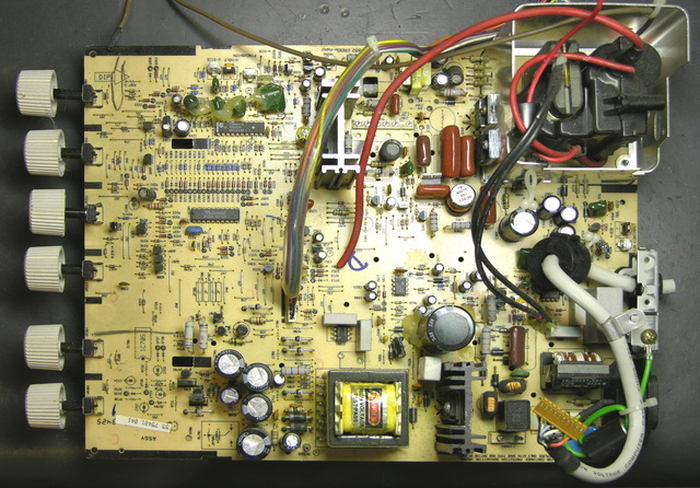
CRT monitor main board

Be sure to discharge the anode cap to the frame at least twice with a couple of big screwdrivers before disconnecting it. Also short large capacitors in the power supply — whatever broke in the monitor may have left no path for the caps to drain.

Dot-matrix impact printers have lots of resistors, maybe a couple of stepper driver chips if you’re lucky, and most likely a bunch of high-power (5A) FETs that ran the printhead, maybe with TTL-compatible FET driver chips. Also one or two large electrolytic capacitors in the power supply, if you’re into that kind of thing.

The printhead carriage rods and slides are great for DIY CNC drill/mill machines . . .

Dead PC power supplies have a couple of good bridge rectifiers, some other rectifier diodes, a few medium-sized electrolytic capacitors, and a bunch of one-foot pieces of really nice 18-gauge stranded wire in a miscellany of colors.
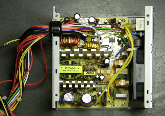
PC power supply

They also have power transistors that you won’t be able to find datasheets for (but they have great heat sinks for TO-220 packages) and toroids that you won’t let yourself throw away but will never actually use.

Live PC power supplies, particularly AT and older, make great bench power supplies, as has been noted many other places. Ignore the bit about soldering in a resistor as a dummy load and just strap an old hard drive on top (plugged in, of course).

If you can find external modems the size of a hardback book and kind of boxy, you’ll get a bunch of resistors and capacitors, a handful of indicator LEDs, and a couple of RS-232 line driver/receiver pairs.
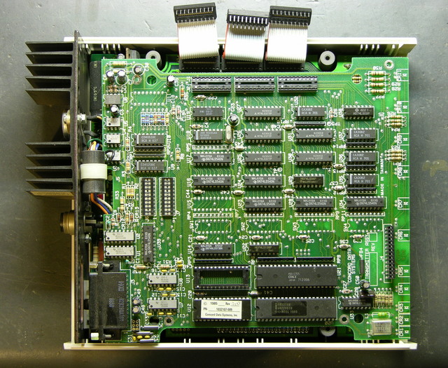
External modem circuit boards

Save the RJ-45 jacks before throwing away dead network cards.
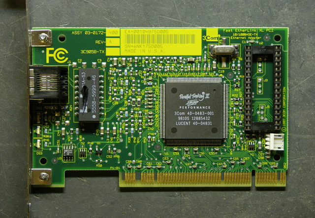
PC network card

Old computer terminals have a bunch of discrete digital logic chips and probably some .1″ headers that are great for terminating fly-cables to plug sensors into your breadboard.

If you’re interested in dabbling in surface-mount work, watch for rackmount network hubs, 10M switches, and 10M fiber media converters. They’ll be old enough that the SMT components are large enough to see and the resistor values large enough to read. They may also have SMT discrete digital logic, PALs and GALs that can be reprogrammed, and SRAMs.
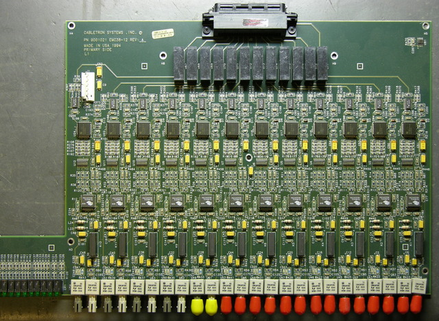
Fiber to copper media converter

Bad Stuff for Salvage

TVs, VCRs, and stereos are going to disappoint you with monolithic ICs and surface-mount components. An old enough stereo may get you a handful of resistors and capacitors, and save the phono jacks if you’re at all interested in tinkering with audio or video.
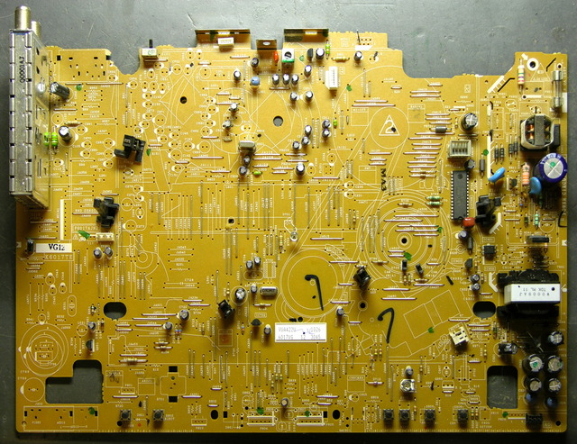
VCR main PC board

Inkjet printers have a couple of motors — maybe stepper, maybe DC — that are fairly strong for their size. All the electronics will be surface-mount, though. Save the wall wart and salvage the corresponding jack if it’s easily removed.

Computer motherboards have been nearly all SMT for quite a while. The battery holder or supercap that preserves the BIOS settings is worth pulling out, and there may be headers/jumpers you can save. If you have a good magnifying glass and room to store the board, set it aside for when you need to find a particular value of SMT resistor.
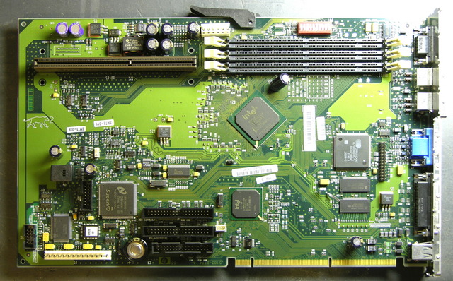
Computer motherboard

Dead CD-ROM and hard drives are full of fascinating things, but not that great for basic electronic parts, since they’re all SMT. CD drives have nice geared/pulleyed DC motors for the tray and tiny limit switches nearby to detect when the tray is in or out, plus tiny DC or stepper motors to move the read head sled.
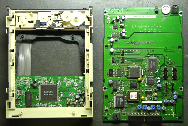
CD-ROM drive mechanical components and main PC board

Disappointing Robo-Bug

Tuesday, December 11th, 2007

I went to Radio Shack yesterday for some patch cords and discovered three 3′ MIDI cables for $13. Score! Bought ‘em.

At the checkout counter, they have these cute little motorized bugs for $10.

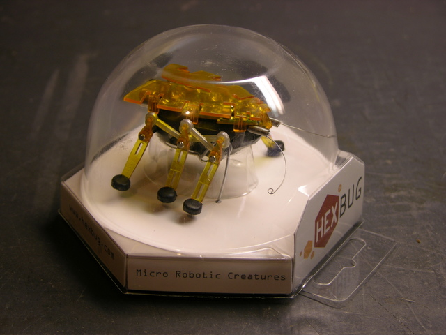
Hexbug in plastic case

I was afraid it’d be lame; but I played with it a bit. When its feelers hit something, it backs up and turns. It sure looked like two motors were being used to control the forward / reverse-turn behavior. Turns out I’m the one who’s lame for getting fooled; but we’ll get to that.

$10 was about my threshold for a bug with two motors and two touch-sensitive antennae. It’d take some tricky rewiring or maybe making a new circuit board, but it should be possible to make the bug a lot smarter. Plus I didn’t really care about the microphone and response to loud noise, and I figured that accounted for a lot of the circuit board, which I could disable or remove.

Plus it’s really compact. The body is only an inch wide and about an inch and three-quarters long; that makes it really cute.

Bought one. Took it apart today.

Pre-Operative Impressions

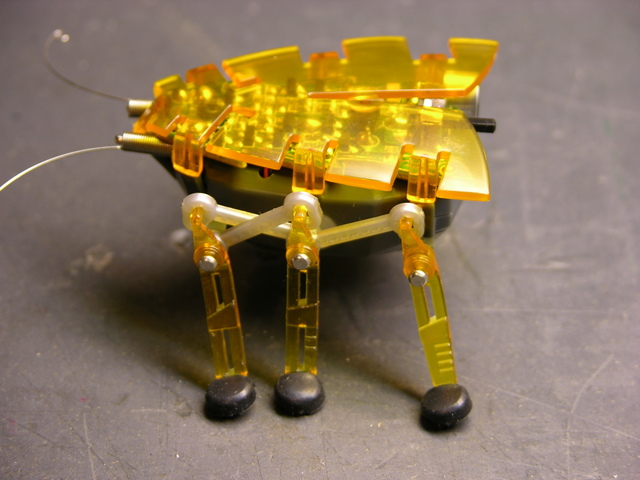
Hexbug standing

The Hexbug is what I call a faux walker — it doesn’t shift its balance to place its center of mass over alternating feet, and each side’s legs only have a single degree of freedom. It’s incapable of falling over, and it could just as well have treads or wheels. It’s still cute — I’m just being clear that I have no delusions about its level of sophistication. Except how many motors it has.

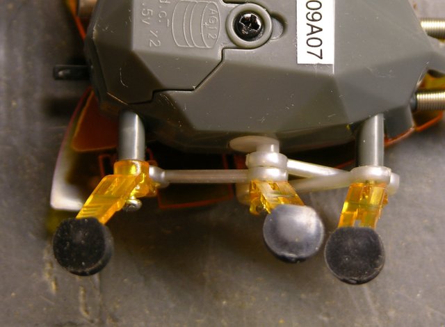
Each side’s legs are powered by a single rotating shaft, shown below. The linkages in the picture above transfer that motion. The front and rear legs move in sync, and the middle leg moves in the same direction but 180° out of phase.

Hexbug motor and linkage closeup

With the bug upside-down, you can see the rotating shaft coming out of the bug body, with an eccentric knob driving the linkages.

The outer legs’ axles are stationary, so the legs just swing back and forth. The middle leg’s axle is attached to the eccentric peg on the rotating shaft, causing the middle leg to move up and down while turning; this is how it lifts its foot to move without dragging.

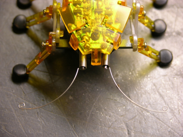
Hexbug antennae closeup

Finally, before beginning disassembly, the antennae are coiled springs positioned around stiff wire, with feelers protruding at the ends. When a feeler presses against something, the coil portion of the spring contacts the wire, closing a circuit and telling the bug to reverse and turn. These are actually more nicely done than other wire feelers I’ve seen — they do a really good job of retaining their shape and position.

Now to Operate . . .

Hexbug standing

The orange wing is press-fitted on, although more tightly than I expected. Each of the six side flaps that bend down, plus one on the front, continues in a peg pressed into a mating hole in the body. I put a flat screwdriver between the PCB and the wing and twisted to loosen each peg, being careful not to crush anything on the PCB in the process.

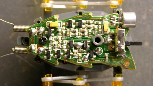
Hexbug PCB

There’s the brain. I haven’t traced the circuit, but I can make a few observations. The solder blobs below and to the right of the grey standoff in the middle of the board are the battery connections, the blobs at the front are obviously the antennae connections, and the blobs in the center of the lower half of the board are the motor leads. Two leads. One motor.

The top of the board looks like it’s audio processing, running from the microphone in the back toward the antennae at the front (since a loud noise and an antenna hit perform the same function) and feeding into the motor drive on the lower half of the board.

Motor and Drivetrain

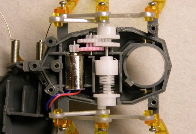
Removing the screw from the PCB and pressing in a latching tab at the back end of the bug (I did it with the batteries already removed, but this might not be necessary) allows the bug’s body to split open, revealing the motor and drivetrain. Motor. One motor.

Hexbug motor, geartrain, and reversing clutch

Look. It’s one motor.

Duh.

The motor leads aren’t very long, so the upper half of the bug is tucked under the front end of the lower half of the bug in this pic.

When the motor is turning “forward” and the white gear at the top of this picture (right-side legs) is moving with its upper teeth going forward, the coil spring at the center is being turned in the direction that makes it “unwind” and expand in length. This forces the cam at the bottom of this picture (left-side legs) to turn with.

When the white gear at the top is moving with its upper teeth going backward, the coil spring is being turned in the direction that winds it tighter, making it contract. This releases pressure against the bottom cam and causes the spring to slip against it instead of forcing the cam to turn.

What Next?

So now I don’t know what to do with this dumb bug.

  • Be a good little consumer and let it wander around my desk until its batteries die or it falls off and gets crushed. Not my style.
  • Mod it for two motors somehow — stick another motor in (hard!) or buy another bug, rip the left legs off both of them, glue their left sides together, and have a double-wide bug with two motors. But that’d require another $10 bug, and one $10 was the max I’d spend for a two-motor bug.
  • Figure out something else cool to do with it. Dunno what.

OR

  • Give it a smarter behavioral system that, within the capabilities of its lameness, emulates a two-motor bug.

The last one is actually kind of intriguing. Right now, when it hits an obstacle, it backs up enough to do about 90° of clockwise turn, regardless of which antenna made contact. So “reprogram” (rewire) the bug to discern which antenna was hit and turn 90° CW or 270° CW accordingly. Because it rotates about its left legs rather than its center, 270° CW is not the same as 90° CCW would be, but it’s as close as we can get.

With a tiny microcontroller on board, it could get more sophisticated yet, turning at other angles, and even doing quick reverses during normal forward travel in order to move in forward curves.

Thoughts?

Dissecting Swag

Tuesday, December 11th, 2007

At the end of October, I attended a national, annual conference on computing in higher education, and they always have a huge vendor expo with lots of swag being given away. These days, my interest really boils down to free t-shirts and what I refer to as LED trinkets (anything flashy); but a couple of other things turned out to be irresistible. So I brought them home and took them apart to see what makes them go.

USB Software Demo Fob

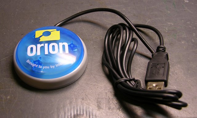
Orion, whoever they are and whatever they sell, snagged me as I was walking past and offered me this “demo on USB.”

Orion USB demo fob

I responded truthfully that I was fascinated . . . although I didn’t point out that I was fascinated merely by the idea of demo-on-USB, and really unfascinated by whoever they are and whatever they sell.

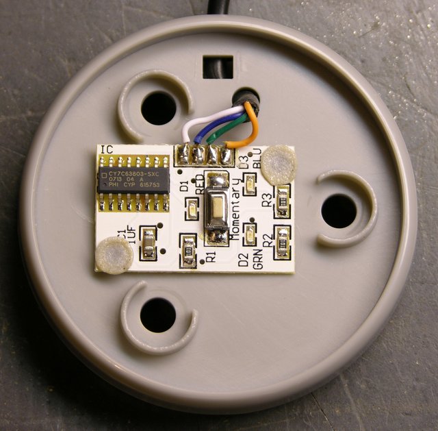
Orion USB demo fob PCB

Inside, the only components are LEDs and their current-limiting resistors, a pushbutton switch, and a Cypress CY7C63803 USB peripheral controller chip. From the datasheet, this thing is an 8-bit microcontroller with integrated USB support, in-system reprogrammability, and 14 (total, configurable) I/O pins in a 16-pin SOIC package.

It’s targeted for use in mice, keyboards, gaming peripherals, barcode scanners, etc., and it strikes me as a really slick little device. It’s available at Digi-Key in single quantities for about $1.45 — seems like there may be some kind of opportunity there, if the development system isn’t prohibitively expensive.

So . . . it seemed unlikely that an 8-bit microcontroller would have an entire software demo on it, which led me to question exactly what the dongle did. I assume it was made to demo on Windows; and even if I had a Windows machine, there’s no way I’d plug this thing in and get pwned.

Instead, I did what any self-respecting geek would do and hooked it to my Linux box, with tail -f /var/log/messages running.


Nov 4 18:17:06 dell2600 kernel: usb 4-2: new low speed USB device using uhci_hcd and address 10
Nov 4 18:17:06 dell2600 kernel: usb 4-2: configuration #1 chosen from 1 choice
Nov 4 18:17:06 dell2600 kernel: input: Cypress Semiconductor, Inc. enCoReII Keyboard RDK as /class/input/input9
Nov 4 18:17:06 dell2600 kernel: input: USB HID v1.11 Keyboard [Cypress Semiconductor, Inc. enCoReII Keyboard RDK] on usb-0000:00:1d.3-2
Nov 4 18:17:06 dell2600 kernel: input: Cypress Semiconductor, Inc. enCoReII Keyboard RDK as /class/input/input10
Nov 4 18:17:06 dell2600 kernel: input: USB HID v1.11 Device [Cypress Semiconductor, Inc. enCoReII Keyboard RDK] on usb-0000:00:1d.3-2

It was automatically detected as a keyboard-class device. Okay. And its little blue LEDs were glowing, glowing, hypnotizing me, luring me . . . press the button . . . it can’t be that bad . . . press the button . . .

rwww.orionondemand.com

Huh. Typed that right into my terminal, as if it were a keyboard.

Looks like it’s trying to go to a URL, but I don’t know what’s up with the “r” in front. I tried “keying” it into vi after hitting Ctrl-v to capture escape codes; I redirected it into od -c as well. Nothing. Just the “r.”

I have to assume on Windows, it does something else — that there’s a keycode my Linux doesn’t recognize that starts up the default browser, or that there’s additional USB functionality sending through another driver that Linux doesn’t support by default. But how it works, in general, is now easy enough to see.

Solar-Powered Flashy LCD Shutter Thingum

LCD swag, light

I didn’t even see these at the show, but after we got back, my boss gave me his.

LCD swag, dark

It’s apparently a picture holder; but in the lower right corner, there’s a little sign that flashes on and off every couple of seconds saying “Confirmed.” (I have yet to figure out what is confirmed, but maybe it’s part of the vendor’s current marketing campaign. Brilliant, that, if you can’t associate the keyword with the company without having seen their literature first.)

My first impression was that there was an EL backlight going on and off. But the glass looked like an LCD . . . and why would they put in a whole color LCD just to display a static graphic saying “Confirmed???” It turns out there’s no backlight, and the LCD is being used as a shutter to hide and reveal a paper graphic.

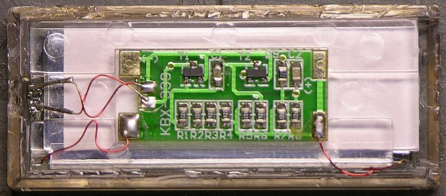
LCD swag circuit board

Here’s what it looks like after prising it out of the frame and opening the clear plastic case. The circuit board has two transistors, and the power source is a narrow strip solar cell hidden along the lower edge of the enclosure.

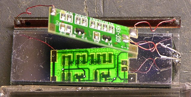
LCD swag circuit board and solar panel

It occurred to me that perhaps the solar cell could be part of the timer oscillator — when light shines through the LCD, the cell builds up enough charge on a capacitor to darken the LCD, which in turn discharges the capacitor and restarting the cycle. Not so, as far as I can tell; the LCD continues flashing with the solar cell out of the case and exposed directly to continuous bright light.

Rather, I assume that the circuit is a simple two-transistor oscillator . . . and that’s about as far as I care to take my analysis. The PCB’s pretty intelligible if anyone wants to trace it out, but I already know enough to satisfy my curiosity: solar cell rather than battery, and LCD shutter rather than backlight.

Replacing My Visor Prism’s Battery

Monday, November 19th, 2007

I still use my Handspring Visor Prism PDA for my calendar, contacts, and some notes and lists. I like the Windows version of the Palm Desktop better than any other calendaring application I’ve seen (way better than iCal), which results in my having a low-end PC under my desk running Palm Desktop, and Synergy to use one keyboard and mouse across my two Mac monitors and one Windows monitor. And I like the color Visor Prism better than my original greyscale Visor because the white backlight makes the screen easier to read than black on grey-green.

The Prism was the first Handspring product to contain an internal, rechargeable Li-Ion battery; and my battery life has dropped over the last five years from weeks of standby / well over an hour of use to a couple of days of standby / a few minutes of use.

I found a replacement battery on eBay for $5.95 plus shipping from enessysales, whom I can heartily recommend. I bought and paid for my battery Thursday and received it tonight (Monday) via USPS. These folks are on the ball.

Battery Replacement

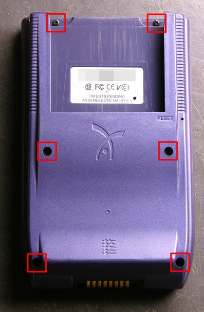
I have a tendency to open things to see what’s inside; but strangely, I had never opened the Prism before. As it turns out, battery replacement was straightforward. Remove the six Phillips screws:

Visor Prism, six screws for disassembly

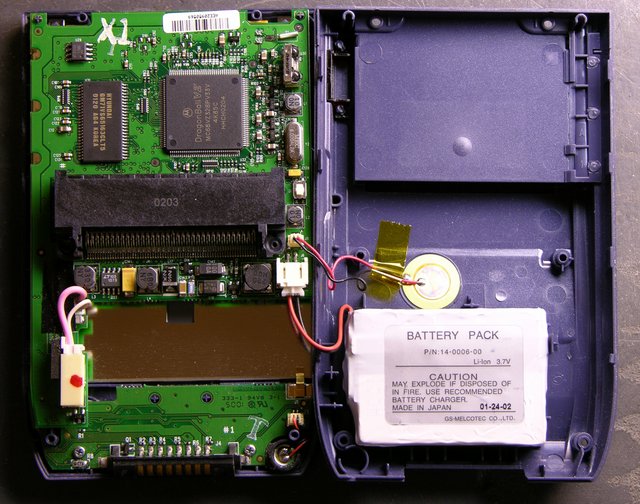
Then gently pry apart the sides with a thumbnail. With the screen facing down, fold the Visor open on the right, with the speaker and battery leads trailing across.

Visor Prism interior

The battery is fastened to the back cover with double-stick foam; so pry it loose, then disconnect the plug.

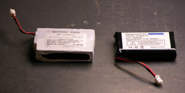
Visor Prism original and replacement batteries

The replacement battery is smaller than the original, but at 1600 mAh, I believe higher capacity. The original battery is also now stuck to my desk with double-stick foam. Errrrr.

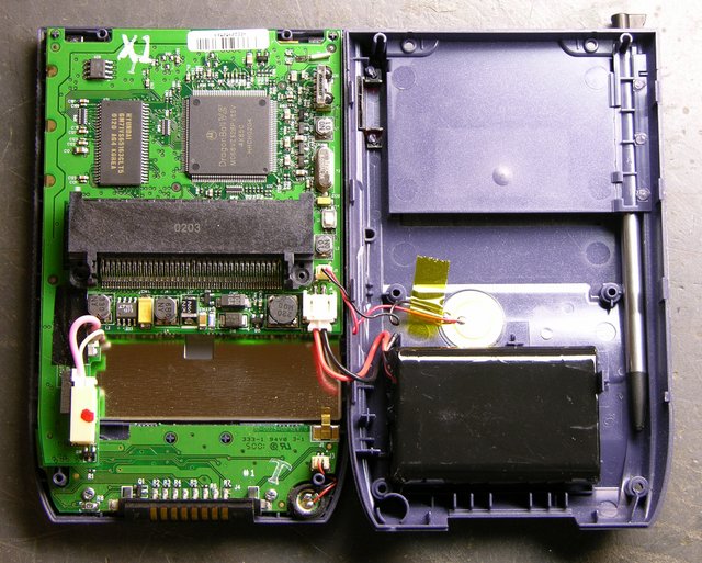
Visor Prism interior with replacement battery

Being only slightly smaller, the replacement really doesn’t have a lot of room to move, so a small bit of foam that stayed behind is plenty to hold it in place.

There’s a small ridge of blue plastic just above the upper left corner of the battery. I had to poke the wires so they went to the left of it before I could close the case, after which reassembly was quite easy.

All Data Lost (As Expected)

The original Visor and Visor Deluxe had small batteries inside to retain memory while you were replacing their AAA cells. The Prism, having an internal rechargeable battery, apparently does not have a memory retention battery. After the replacement, it came up in touchscreen calibration mode, with date and other preferences unset and all my programs and data gone.

No matter; I’ll resync at work tomorrow. It’s a good opportunity to make sure I’ve backed up my few third-party programs correctly. (I use FileZ to twiddle the backup bits on various softwares, hopefully to make my backup strategy smarter than the default, but one never knows until one tries.)

And I’m looking forward to checking the new battery life.

Update: All applications and data restored as expected.