Archive for the ‘Inside’ Category

Hammond XB-2 Drawbar Decoding Diagnosis and Repair

Saturday, March 5th, 2011

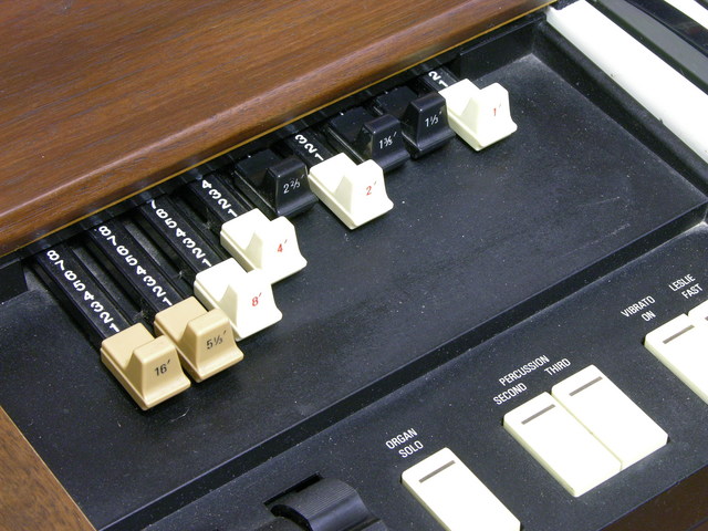
A couple of weekends ago I took the two XB-2s that I had (at the time) over to Ron’s shop to have a little more room to spread out and test things. Like real Hammond tonewheel organs, the XB-2 has “drawbars” that represent different harmonics (or subharmonics) of the fundamental frequency of each key being pressed; you draw out the bars to mix different amounts of the different harmonics to get the timbre you want. This is additive synthesis at its most visceral.

Hammond XB-2 drawbars

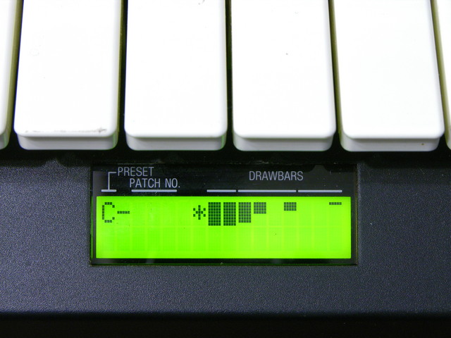
On the XB-2, the drawbar positions (either live or recalled from memory) are displayed on an LCD below the manual (keyboard). In live mode, the bar graphs move in and out in synchrony with the physical drawbars.

Hammond XB-2 drawbar display

On one of the two XB-2s, the LCD bar graphs didn’t match the drawbars — a couple of drawbars appeared to work properly, but some didn’t work at all and others moved multiple bar graphs on the display. Since the drawbar decoding is a relatively independent section of the organ, it seemed like an easy repair to tackle first.

Hammond XB-2 drawbar schematic

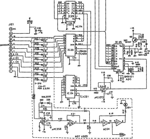
The drawbar’s wiring harness plugs into the main board on J121, at the left of this section from the service manual. Each drawbar is a detented slide potentiometer, so variable voltages are arriving on J121. The section enclosed in the dotted line and marked not used truly isn’t populated on the circuit board, so I omit it from discussion.

The nine analog drawbar voltages are delivered to IC23 and IC24 (TC4051 analog multiplexers). The multiplexers receive their enable and select signals from the output of IC29 (74HC174 hex D flip-flop) which is latching signals previously delivered from the system data bus. (In other words, the 74HC174 is the drawbar select register; its own address is decoded elsewhere in the schematic.)

The chosen (enabled) TC4051 analog mux selects which input to pass to its output on pin 3, which is then op-amp buffered and delivered to the input pin of IC25 (BA9101 analog-digital converter). When selected (more system address bus decoding), the ADC writes the digital value of the drawbar’s position onto the system data bus.

Side note: For the drawbars only having nine detents (0-8), IC25 sure delivers a lot of bits of ADC resolution to the data bus.

I put a scope on IC23 (analog mux)’s output pin and I was able to view on the screen the time-division multiplexing of the drawbar positions (analog voltages) onto the single line going to the ADC. It mostly matched what I saw on the LCD, although there were some quirks with a few of the drawbar time divisions appearing narrower than others. Ignoring the odd widths and recording which drawbar occupied which time division:

Drawbar Time-Division Multiplexing Behavior
Drawbar 16 8 4 2 1 5 1/3 2 2/3 1 1/3 1 3/5
IC23 Pin 13 14 15 12 1 5 2 4 (IC24)
IC23 Input Good MB 0
(000)
1
(001)
2
(010)
3
(011)
4
(100)
5
(101)
6
(110)
7
(111)
(IC24)
Bad MB 0
(000)
1
(001)
7
(111)
7
(111)
0
(000)
1
(001)
7
(111)
7
(111)
(IC24)

On the working XB-2 motherboard, the drawbars were selected and sampled in numerical order. On the broken motherboard, as you can see, any time the analog mux’s select bit A1 was enabled, the mux behaved as though bits A2 and A0 were enabled as well. Further, select bit A2 didn’t work on command as it should when drawbars 4-7 should have been chosen.

4051 Address Pins
Name C B A
Function A2 A1 A0
Pin 9 10 11

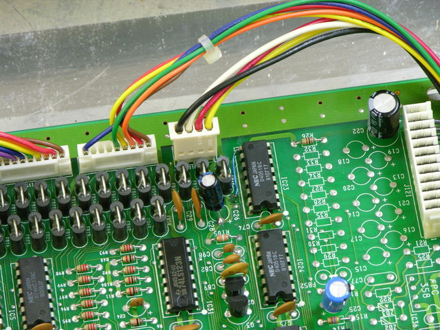
It could be a bad 4051 mux; but as we had already replaced a leaky electrolytic capacitor in the neighborhood, it seemed worth another look at the circuit board first. The 4051′s select lines are on pins 9-11, and what’s this?!

Hammond XB-2 main board, drawbar section

I became suspicious of a damaged via on a trace that turned out to connect to pin 9 (A2). A continuity test showed that the via — even its top side — was no longer connected to IC23; the trace up to the via had been eaten away by the leaking capacitor. The via — even its top side — did have continuity to its next stop on the PCB, so the via itself was intact.

Ron heated the solder that had wicked into the via during reflow, inserted a piece of wire-wrap wire, and soldered the other end directly to IC23 pin 9. The drawbars now work perfectly. I suspect the floating select input on the CMOS mux was picking up enough signal from the PCB trace inductively coupled to its neighbor to trigger.

My hypothesis is that the previous owner put the keyboard away because of larger (ROM / CPU / Muse) problems; the capacitor leaked and damaged the drawbar multiplexer trace while it was sitting idle; and the owner never even knew about the drawbar problem. At any rate, it was easily fixed and the troubleshooting was a rewarding mental exercise.
Water and Electronics

Friday, February 11th, 2011

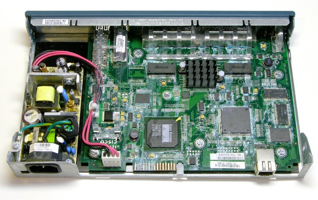
Three days after we upgrade an ancient switch in the campus golf course headquarters, a supply pipe breaks overhead and pours water into our new switch. It’s “environmentally hardened,” but that doesn’t seem to cover immersion.

As a state university, we’re self-insured and there’s no way we’re getting a T&M refurb from the vendor on water damage, no matter how generous they may be. So I’m getting nothing for this dead switch and I may as well see whether there’s any hope of cleaning it.

Cisco 2940 switch interior after water damage

Oh. Nope, not really.

(more…)

Fixing Jeremy’s Ford Mach 460 Bass Amplifier

Saturday, October 2nd, 2010

Sometimes you get lucky.

Ford Mach 460 bass amplifier

My friend Jeremy has a 1995 Mustang that had the factory premium sound system in it when he bought the car used. The CD player was broken and he had the head unit replaced within a couple of weeks of owning the car. He later added a subwoofer.

I’ve always thought the stereo lacked clarity in the bass, and the head unit and EQ have had some quirks. Recently Jeremy pulled the head unit and found all sorts of interesting techniques used by the aftermarket installer that will be the subject of a later monologue … but one of the things we discovered is that the amplifier for the door woofers wasn’t working at all. Swapping it with the amp for the rear deck woofers caused them to go silent and the (shot) door woofers to work again (after resoldering their cut cables).

Turned out to be a delightfully easy fix.

(more…)

Repairing a Crumar T1 Organ Swell Pedal

Friday, August 6th, 2010

Crumar stack

Both my Crumar T1 and T2 “portable” organs (the lower two cases in the stack) came to me without swell (volume) pedals. Each has a rotary potentiometer on its control panel for master volume, but I really want to be able to change the volume dynamically while playing. I’ve been using a Dunlop volume pedal (built into a rocker case identical to the CryBaby wah) on the organ’s output; but (at least when used with the organ) all of the pedal’s action is in about the lower quarter of its physical range, so it’s very finicky to use.

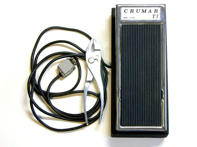
Crumar T1 organ swell pedal

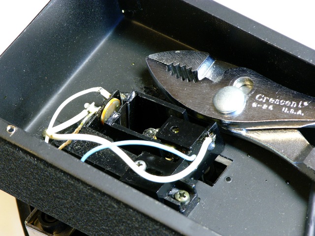
I recently bought this original T1 swell pedal on eBay, listed as untested / project. That usually means tested / didn’t work / can get more money if I don’t admit that I already know it doesn’t work; but I figured I could fix whatever was wrong with it. And I have.

Crumar T1 organ swell pedal photoresistor enclosure

(more…)

Repairing a Bad Horsie 2 Wah Pedal with Power Damage

Wednesday, July 7th, 2010

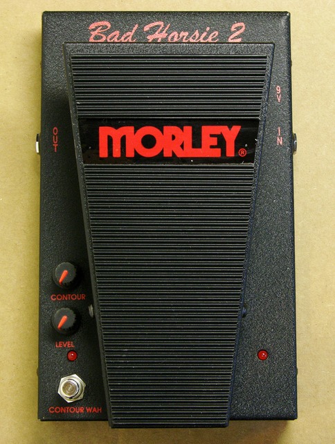
Bad Horsie 2 wah pedal

I recently ran across on Craigslist a

Bad horsie 2 that was plugged into the wrong power supply and messed up, and needs some minor electronic work.

I was intrigued by the challenge (I’m such a sucker for broken things, dang it) and bought it. When the seller and I exchanged the pedal for my cash, he remarked that he read on a forum that it probably just needed a resistor changed, and that if I were handy with a soldering gun I could probably do it myself.

Uh huh. Resistor.

Let’s dig in.

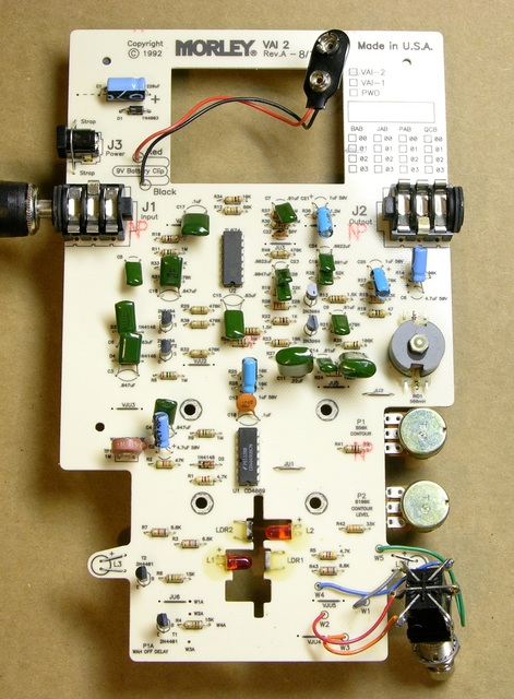
Bad Horsie 2 wah pedal circuit board

The circuit board has a hole in the top for a foam battery “cage” attached to the enclosure, something clever that I haven’t seen before. And it had no obviously damaged components.

(more…)

Installing Batteries in a Liebert GXT2-2000RT120 UPS

Sunday, June 27th, 2010

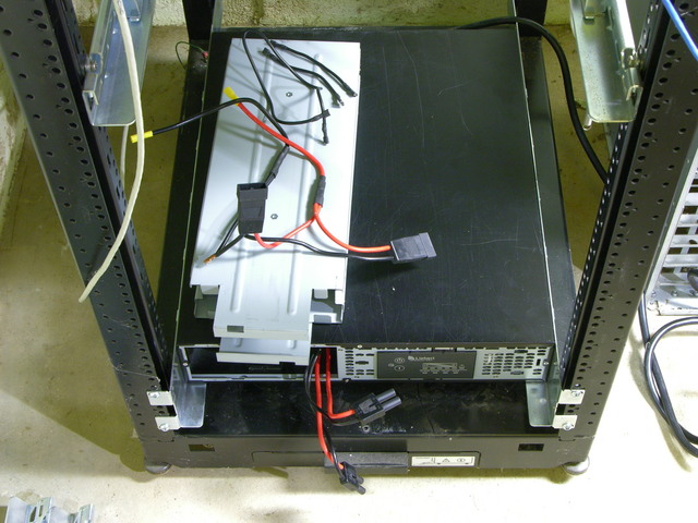
A while back, I bought a secondhand Liebert GXT2-2000RT120 uninterruptible power supply (UPS) on eBay. The GXT2 is a series of online UPSes, meaning that the output power always comes from the inverters off the battery bank; it doesn’t switch from utility power to battery power like an offline UPS. Besides eliminating any possible switchover glitches, online UPSes always deliver conditioned power at a constant voltage. The 2000RT120 is a 2000VA unit with 120V output — large enough to power all my servers for a good little while.

Liebert GXT2-2000RT120 UPS with battery cage disassembled

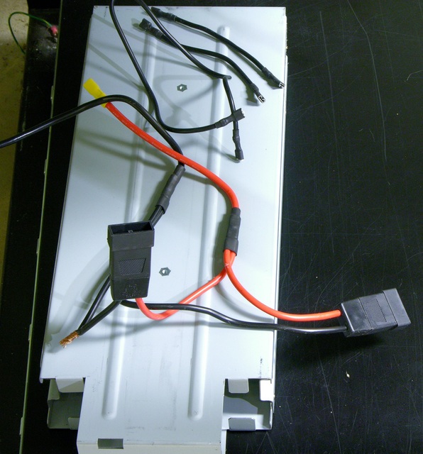
The batteries were due for replacement and the seller removed them to save on shipping costs. I got a UPS with a set of wires and no instructions on how to connect them.

Liebert GXT2-2000RT120 UPS battery wiring

Also one of the wires was compromised … but since it appears to be a ground wire, I figured no big deal if it shorts out against the cage. KIDDING!

Yesterday I figured out the wiring, installed batteries, and got the UPS set up in my server rack.

(more…)

Lacing the x0xb0x Wiring Harnesses

Sunday, June 6th, 2010

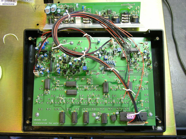
This isn’t part of a normal x0xb0x build so I didn’t throw it into my build notes, but I had fun figuring out how to route and lace the x0xb0x’s wiring harnesses. I know lacing is overkill for this; but without some kind of cable management, the individual wires of each cable wouldn’t even stay together. Had the kit included ribbon cables, I wouldn’t have bothered.

Planning the Paths

First pass at x0xb0x cable routing

Besides the obvious goal of keeping the wires tidy, my main goal was to position slack in the cables so that the back panel could be lifted out of the case and set to the rear, allowing full access to both circuit boards, without disconnecting anything.

Before doing any real lacing, I mocked up the cable path to make sure everything would work. My first attempt, here, had enough length for the J3 bundle from the lower right of the main board to the right end of the I/O board; but J7′s wires coming from the left edge of the main board looped around too much before heading to the I/O board and didn’t reach their destination.

(more…)

Building the x0xb0x

Sunday, June 6th, 2010

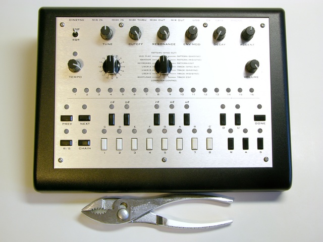
As I noted previously, I recently got a x0xb0x kit. The x0xb0x is an open-source-hardware replica of the 1980s Roland TB-303 bassline synthesizer (and sequencer) that was influential in the development of acid house music. Limor of Adafruit Industries and a mysterious, anonymous German studied the TB-303 schematics and measured the behavior of its now-rare semiconductors and designed a replica with the same analog circuitry and new digital features, including MIDI I/O (supplementing Roland’s pre-MIDI “DIN sync”) and simpler sequencer programming.

Assembled x0xb0x, top view

Adafruit produced x0xb0x kits in batches of 100 as Limor was able to track down enough “rare parts,” order circuit boards, and assemble the common parts into kits. I’d been on her waiting list since 2008, so was terribly disappointed when she officially announced what we had all come to realize anyway — that tracking down the rare parts was becoming enough of a hassle, she wasn’t having any fun doing it and wasn’t going to produce any more kits.

Happily, Limor announced shortly thereafter that thanks to Adafruit’s open-source hardware license, James Wilsey of Willzyx Music in Taiwan has taken up the torch and would shortly be offering x0xb0x kits.

(more…)

Repairing a Patch Cord

Monday, May 31st, 2010

Recently a couple of pieces of audio processing equipment I’ve bought used have had bad left channels. After recognizing the pattern, I finally thought to swap out the patch cord I had left plugged into the “test” channel on my keyboard mixer, and voila! Left channels fixed.

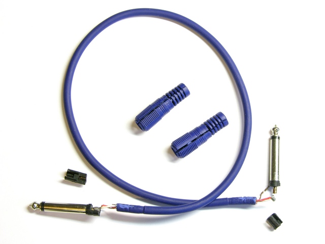
Audio patch cord, disassembled

I’ve always been curious about the construction quality of commercial patch cords — just how good are the connections buried under those lovely molded jackets and strain reliefs?

Naturally, the faulty end was the last one I disassembled. (Logic joke!)

(more…)

Replacing a Broken Power Jack on a DBX 266XL Compressor

Sunday, April 11th, 2010

I recently bought a DBX 266XL audio compressor/limiter on eBay. The seller described it thus:

Has light scratches, small amount of rack rash, in perfect working condition- no issues whatsoever. Has been used in my guitar rig for the past several years with no problems.

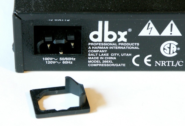
Broken C-14 power jack on DBX 266XL compressor

It arrived oddly but adequately packed and … as you can see, not in perfect condition. I would go so far as to say it had issues. I suspect had I tried to use it, I would have had problems.

Well … I could complain to the seller, who would tell me it was damaged in shipping, and then I could try to deal with the USPS who I don’t think broke it, and I could spend a lot of time and frustration and maybe get some money back and probably end up with no compressor. Or I could just fix it myself and have a little fun in the process.

(more…)