Wired 3: Please Wait (Friday Night!)

April 23rd, 2008 by Keith Neufeld

I haven’t posted anything in a long time because I’ve been:

  1. Lying on a beach in Jamaica.
  2. Hauling off treasure troves of vintage electronics components from a secret lair off of Highway 77 in northeast Kansas.
  3. Utterly consumed by working with our Technology: Art and Sound by Design students to get our final show ready for Friday night.

You guessed it; it’s option C, which WordPress’s stylesheet renders as 3.

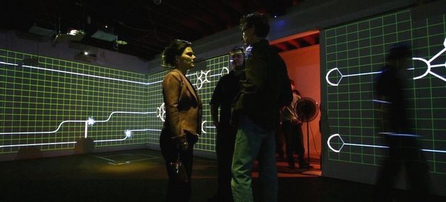
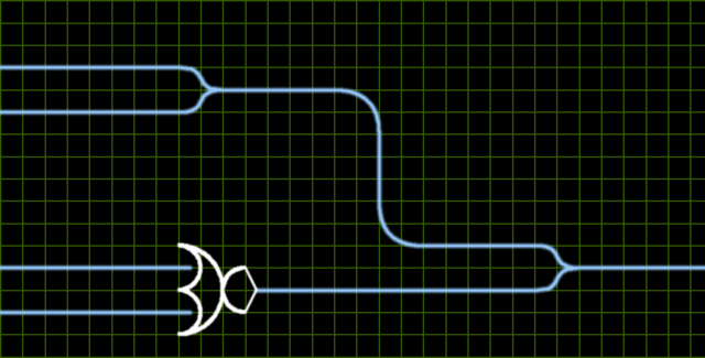
We’re taking over WSU’s Shift Space gallery for April’s Final Friday gallery crawl. We have ten projectors covering the gallery walls in 360° video surround and displaying a giant, abstracted circuit in sections like this:

The student technology projects (abstract LED display, traffic light and control button, computer-controlled archival video footate, floor pressure plates) interface with the “circuit” to control fireball “bits” moving about on the wires and through the gates. Another student has prepared ten-channel audio with both spatially-located sound effects for circuit elements and ambient sound/music to set the tone for the show.

All electronics are done on Arduinos (probably about six in use for the whole exhibit); and PC interfacing, circuit control, and audio are done in Pd.

If you’ll be near Wichita Friday night, I’d love for you to drop by and introduce yourself — ask around for Keith and someone will point you to me.

Shift Space is at 800 E 3rd St N, and we’ll be open Friday night only from 19:00 to 23:00.

Inside an Airport Extreme Card

March 6th, 2008 by Keith Neufeld

I’m piecing together a wireless notebook computer for my wife (her first!), and so far it comprises an iBook from Cort with a crashed hard drive, a Toshiba drive from Jeremy, and a refurbished Airport Extreme card from Apple. Silly eBayers take note: You can get the card straight from Apple for only $29 plus shipping; and the shipping from Apple is only $4, not $9.99.

Cort had cannibalized the Airport card out of the iBook to trade for a dead card in another machine, so the iBook came without any wireless. Jeremy had a dead Airport card that he offered me, and I figured I’d at least see whether I could revive it. It didn’t even show up in System Profiler, so I didn’t expect much likelihood of success, but it was worth a quick look for loose connections.

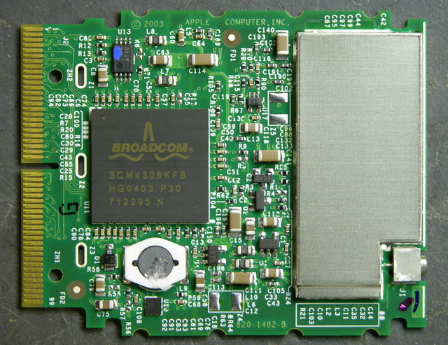
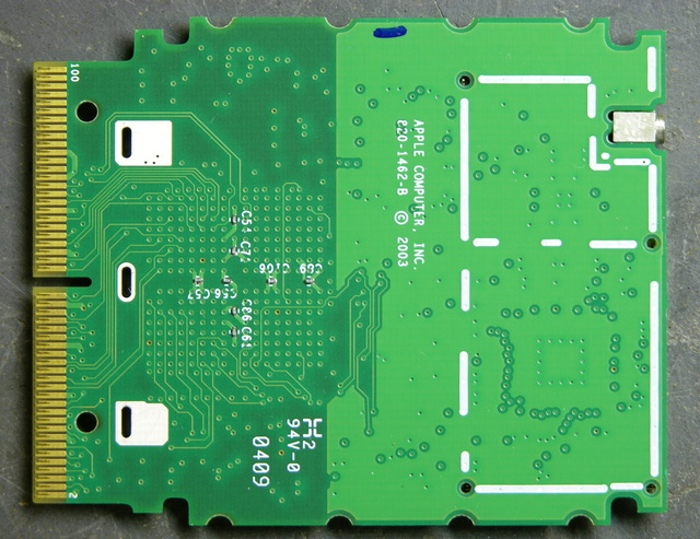
It turns out I was extremely unlikely to have been able to find anything that I could fix, and indeed I didn’t, so I ordered the refurb card tonight. But since I can’t find any pictures online of the inside of an Airport Extreme card, I thought I might as well post what I took.

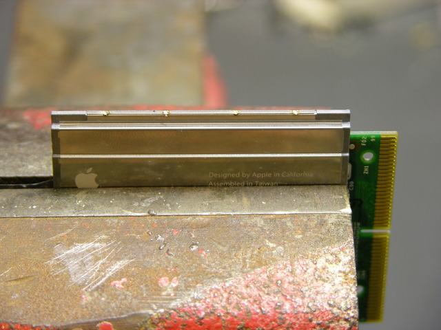
The top and bottom plates of the card are spot-welded together along the edges, so the first step was filing out the welds with a rat-tail file. After that, there were still some tabs to pry out before it could be opened, but they were fairly easy.

And that’s what there is. Nothing in there really subject to stress from normal use or jostling. I looked it over with a magnifying glass anyway, but nothing leaped out at me. I’m guessing the Broadcom chip bit the dust, for no reason I’ll ever know.

I’m fascinated by the tiny capacitors. I measured them at about 20 x 40 mils, which makes them 0402 packages.

The caps on the back side are even smaller (and harder to measure accurately). I came up with about 10 x about 20 mils, which is 0201. Good lands, those are small.

Now I want an excuse to try to solder one. ;-)

Homebrew SMT Probe Tweezers

February 23rd, 2008 by Keith Neufeld

Closeup of SMT probe tweezers in use

Some surface-mount resistors have their values printed on them, but all 1206 and smaller SMT capacitors that I’ve seen are completely blank. The only way to determine their value — after salvaging, that is — is to measure them.

My multimeter has a capacitor tester, but its connections are slots in the body of the meter rather than the regular probes, so it doesn’t work at all for SMT capacitors. (In fact, most salvaged capacitors’ leads are much to short to make contact with the meter’s sockets.) Lately I’ve been plugging a couple of long wires with tinned ends into the meter so I can use the other ends to check the values of SMT capacitors on my workbench.

This is a pain.

Ever since I started salvaging SMT components, I thought it’d be great to have a pair of tweezers wired as meter probes — grab the component, pick it up to put away, and check its value all at the same time. There actually are such things available, but the ones I’ve found start at $35 with a custom connector for that manufacturer’s meter. Not much to my liking.

I figured on building my own, maybe by finding a pair of plastic tweezers and gluing some kind of metal foil to the gripping surface. But what kind of metal? I was thinking about this on the drive to work Monday. Copper oxides rapidly and wouldn’t make good contact in the long term; so does solder. Silver would probably be okay. Gold would be perfect, but I have no idea where to get . . . wait a minute. Sure I do.

Circuit board about to be sacrificed

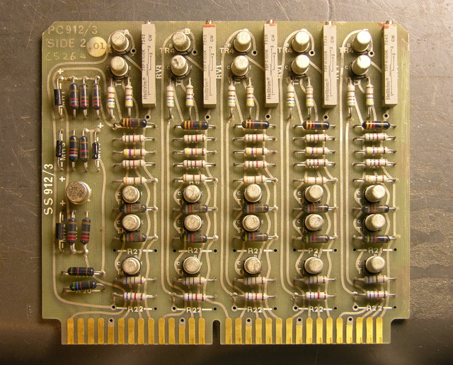
Monday night I sifted through my junk boxes and found a sacrificial circuit board with a nice, wide, gold-plated .156″-spacing card-edge connector on it. I desoldered everything from it the hard way — with a soldering iron — because this time it was about preserving the board rather than removing components as fast as possible.

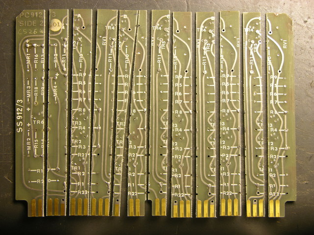
Circuit board cut into strips

Tuesday I took the stripped board to the lab at school and used the PCB shear to cut it into strips, many of which are almost straight. That night I cut a pointed shape onto the end of two strips on my scrollsaw, doing a terrible job. I did slightly better on the next ones.

I used the bench disc sander to smooth them out and narrow the points to the width of the gold strips, then bevel the edges near the tips so the edges are sharp like a knife instead of thick like a PCB edge — it makes it easier to pick up very not tall SMT components. I also sanded the tip’s angle back from 90° to about 60°, since I’ll be holding these at an angle from my hand down to the workbench.

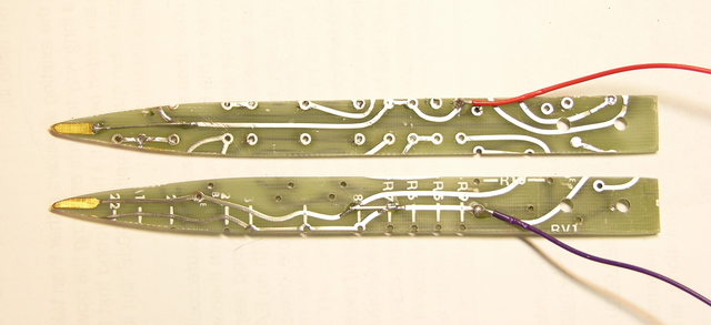
Two halves of SMT probe tweezers, wired

This afternoon I wet-sanded them very smooth, both faces and edges, then soldered a couple of jumper wires so I could use the existing traces to get from tip to handle, and soldered on two lead wires.

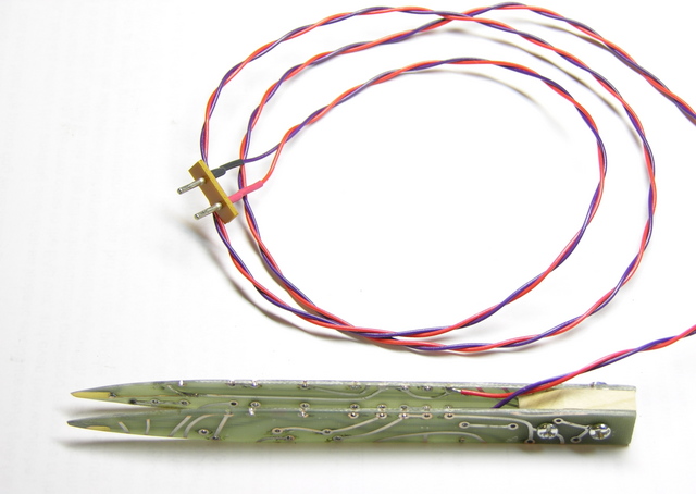
Completed SMT probe tweezers

I taped the points together in alignment, clamped the handle end in a vise with a maple chunk in between, drilled holes through the works, and bolted it together. I had to cut one trace to keep it from contacting the bolts — it wouldn’t have shorted the two leads together, but I still didn’t want the bolts “live” on either side of the connection.

At the far end, I soldered to a salvaged plug (something from a CRT monitor yoke PCB, I think) to fit into the capacitor test slots on my meter.

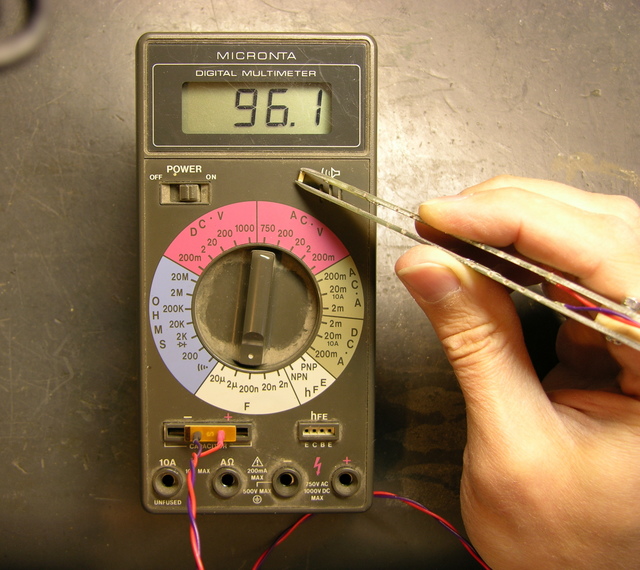
SMT probe tweezers in use

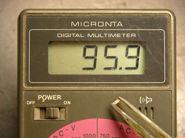
It works very nicely. The tweezer adds about 50pF to my measurements when it’s wide open, 60pF when I hold it as closed as I can without shorting; so probably 50pF when I’m holding a capacitor in it. That’s only a .05% error on the .1μF SMT capacitors I have in abundance, and I bet my meter itself is two orders of magnitude less accurate than that, so it really doesn’t bother me.

I think I have the jack that mates with the plug, and I want to build an adaptor to banana plugs so I can use this to double-check SMT resistor values, too.

Now I’m out of excuses not to put away all the SMT chips sitting out on my workbench. :-)

My First Arduino Shield

February 17th, 2008 by Keith Neufeld

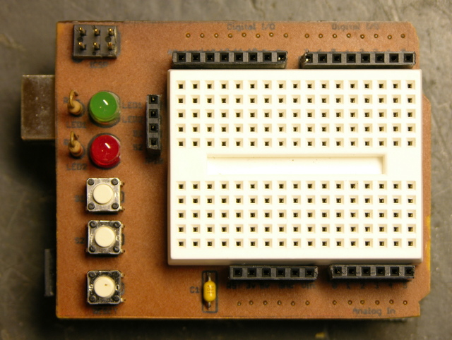
An Arduino “shield” is a PC board made to plug into the top of the Arduino, covering it (hence the name) and extending the Arduino signals to provide some extra functionality. Shields I know about are prototyping shields (“protoshields”), with a tiny breadboard on top; motor control, with H-bridge drivers to run motors, servos, and steppers; and ethernet, with a Lantronix Xport ethernet interface onboard. (I know there are shields from places other than Adafruit, but I really like supporting Lady Ada’s open-source hardware lifestyle, so I tend to look there first.)

After getting my Arduino, I had thought about getting a protoshield, but dismissed it pretty quickly — it seemed to me that the tiny breadboard on it would be too small to be useful for anything complex enough to be worth using the Arduino for. But Friday the Arduinos arrived for class, I agreed to do a demo/intro on Monday, and I realized it’d be a lot easier to do on a protoshield than on a separate breadboard.

With no time to order one before Monday, I had to construct my own over the weekend. I started with Lady Ada’s EAGLE schematic and board files (Creative Commons 2.5 Attribution Share Alike) and hacked them up for a single-sided board that I could etch quickly and easily. I took out her solder prototyping area, moved headers to align better with my tiny breadboard, changed up the LEDs and pushbuttons, and generally did enough work that I’m not sure I saved any time starting with an existing design. :-)

Homebrew Arduino protoshield

Here’s the result — ugly but very functional. I generally use breadboard wires cut and bent to length, so it matters to me that the header sockets are aligned with the breadboard columns and spaced a multiple of .1″ away. It works out very nicely.

Silkscreen Toner Transfer

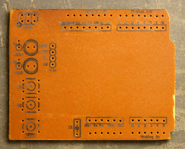
Worth noting is that I used Cort’s idea of iron-on toner transfer for the silkscreen layer on the top side of the board.

Arduino protoshield PCB with iron-on silkscreen

After the copper is etched, the etch resist cleaned, the board tinned if you’re tinning, and the holes drilled, you print the silkscreen layer and do an iron-on toner transfer just like you would for etch resist. The main difference is that for appearance’s sake, you really want to get all the paper fibers scrubbed off of the toner — I probably spent half an hour in the sink with the toothbrush getting it clean.

I think the method is great; it’s just this instance that’s less than perfect. For one, this PCB is very dark, and the black toner doesn’t show up well; it’s much more readable on lighter boards. For another, the font is really smaller than is advisable for a toner transfer — I’m surprised it actually worked as well as it did.

It’s a very nice change to have labeled connections on a homebrew PCB.

Using It

I practiced my spiel tonight for class tomorrow, starting with the Arduino “Blink” sketch flashing the onboard LED, then:

  • plugging in the shield and jumpering in the green shield LED to blink as well
  • jumpering in the red LED and updating the sketch to alternate green-red-green, etc.
  • plugging a common-cathode RGB LED into digital pins 9-11 and updating the sketch to alternate red-green-blue-red, etc.
  • writing a pulse() function that uses analogWrite() (PWM output on pins 9-11) to fade an RGB color from dark to bright to dark and updating the sketch to pulse red-green-blue-red, etc.
  • wiring three more pushbuttons to digital pins 0, 3, and 6 (LOVE the ATmega’s internal pull-up resistors!) and changing the sketch to pulse a color dark-bright-dark on demand

It’s all pretty easy stuff, so the idea is that I’ll be able to do it while maintaining a stream of patter. We’ll see how that works out. :-) Still, it’s a nice introduction to a few of the capabilities of the Arduino and to how easy it is to just try things when you have a breadboard and a nice microcontroller development system.

So Do I Like It?

Using the protoshield tonight has convinced me that it’s great for a tiny demo, and too small to be useful for real work. :-| I’m not complaining, though; it’ll be fun to have around.

One thing that would help is the addition of a ground bus at the bottom — I waste a lot of column space leapfrogging ground to everywhere I need it. There’s room on my board that I’ll add a ground row on V2.

Credits

Original shield design by Lady Ada

PCB stock from Slim

Tiny breadboards from terminalcity

Iron-on toner transfer “silkscreen” method from Cort

LED Calculator Prototyped with LCD

February 8th, 2008 by Keith Neufeld

I still want to find a small LCD module for the LED calculator, so I can fit the whole thing into a box with a footprint about the size of a deck of cards. But for prototyping, I have a stack of 2×16 LCD modules about 3 1/2″ wide (viewable about 2 1/2″) from Slim, and Wednesday night I got one hooked up and working.

They’re Optrex DMC-16207 modules, and they seem to be using the Hitachi chipset that everyone uses, or at least an equivalent, although I didn’t know that at the time. Searching online, I had a hard time finding data on this exact module, but came across a mechanical drawing, a module user’s manual, and finally a full datasheet.

Interfacing the Arduino and LCD

I dived in and wrote my own LCD interfacing code. I found out in retrospect that there are several other Arduino LCD interfacing projects out there:

But all of them are using hard-coded delays to pause while the LCD processes commands, rather than checking the busy flag. To be sure, I’m doing the same thing right now in my first draft of the code; but I’m going to go back and clean it up to do it right.

Also, I haven’t checked all of them, but at least one is using digitalWrite() to manipulate each bit of the port register individually. Since I’m dedicating eight Arduino lines to the LCD’s I/O port, I can write the port register as a byte rather than twiddling individual bits, saving time and effort.

My goal will be to write a nice library module/class that encompasses these different approaches (8-wire vs 4-wire, busy flag vs hard-coded delays, read/write interaction vs hardwired write-only) and presents a clean interface to the programmer to select the options. Of course, for now, I just wanted to get it up and running.

I found this ATmega to Arduino pin mapping, which confirmed that Arduino digital lines 0-7 are PORTD lines 0-7. And the Arduino port register reference shows that DDRX and PORTX are defined as Arduino variables; so writing to a port is as easy as PORTD = $ff . It’s very nice that they left those low-level features exposed, even though in most cases it’s better to use the higher-level interface for portability.

Calculator Prototype

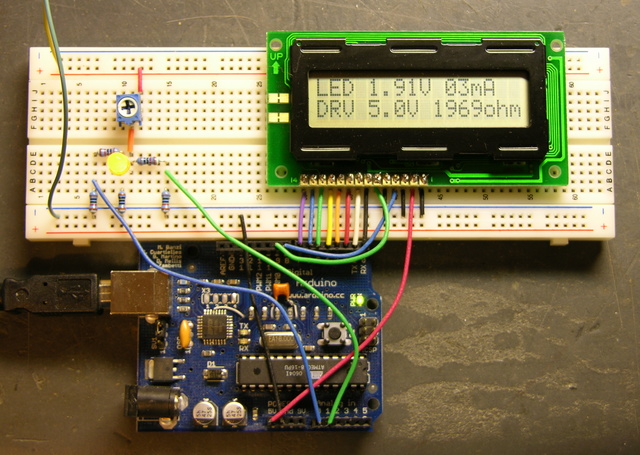
So here’s the work in progress.

LED calculator prototype with LCD on breadboard

The Arduino is getting power from USB and supplying 5V power to the LCD. The LCD contrast is hard-wired to ground. Although it actually looks pretty good right now, I’ll want to put in a potentiometer to adjust contrast. And I’m still using my bench power supply to run the LED circuit at 9V.

I don’t have a method built to select the voltage of the target circuit — the software is assuming 5V for now. The easy thing to do would be pushbuttons to bump the desired voltage up and down. It’d be kind of fun to do it with a spinny-wheel, although I’m not sure how much that would increase the cost, and I’m concerned about overengineering this thing if I really want to offer it as a kit. Maybe another potentiometer is a good compromise.

However the target voltage is selected, I need to determine the selectable range (which could of course be overridden by an owner with an AVR programmer). I’m thinking 3 – 15V in .1V increments. Is that enough?

LED Calculator Breadboarded

February 2nd, 2008 by Keith Neufeld

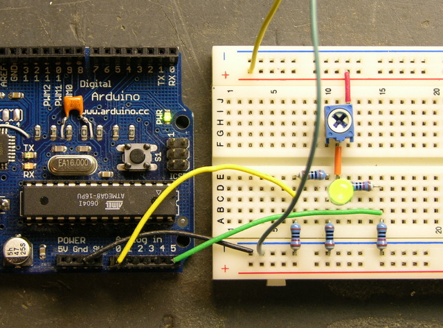
After receiving some encouragement, I went ahead and breadboarded the measurement circuit for the LED calculator. Someone may suggest a better way to do it, but here’s what I’ve been carrying around in my head:

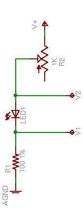
LED calculator drive circuit

R2, a 1KΩ potentiometer used as a variable resistor, controls the LED brightness. R1, a precision 100Ω resistor, limits the maximum LED current and acts as a sense resistor.

By measuring V1, we can calculate I1 = V1 / 100Ω. Since ILED = I1, we’ve determined the LED current. And VLED = V2 – V1, so we can determine the LED voltage drop as well.

The value of R2 isn’t critical. With a supply voltage of 9V and a very low LED drop of 1V, a 1KΩ variable resistor allows us to test LED currents down to (9V – 1V) / (1KΩ + 100Ω) ≈ 7mA, which is probably low enough for most applications. To be able to test lower, increase the range of R2.

Test Measurements

I built this much of the circuit and took measurements of a few different LEDs at a few different brightnesses, to make sure the potentiometer would really work the way I expected, and that I hadn’t made any stupid mistakes in the voltage calculations.

Color V1 V2 VLED ILED
green .71V 2.70V 1.99V 7mA
2.00V 4.04V 2.04V 20mA
3.45V 5.55V 2.10V 35mA
red .73V 2.55V 1.82V 7mA
2.00V 3.88V 1.88V 20mA
7.28V 9.24V 1.96V 73mA
blue .61V 3.61V 3.00V 6mA
1.12V 4.23V 3.11V 11mA
2.00V 5.27V 3.27V 20mA
5.56V 9.24V 3.68V 56mA

The measurements make sense — each LED’s forward voltage drop increases slightly as the current increases. If I remember my semiconductor theory correctly, that’s called the ohmic region of operation, in which a diode behaves like a very low-valued resistor.

Automating the Measurement

In a self-contained LED calculator, the voltages will need to be read by a microcontroller, which will also drive an LCD. For now, I used my Arduino and had it send results to the host computer.

Depending on the position of potentiometer R2, V2 can range up to the supply voltage of 9V (or whatever); and V1 can range up to the LED’s forward voltage drop less than that. I’m pretty sure the microcontroller’s A/D converters don’t like inputs over 5V, so I needed to divide V1 and V2 to lower their ranges before feeding them into the ADCs. I used two pair of precision 10KΩ resistors for that.

LED calculator measurement circuit

All put together on the breadboard, it looks like this.

LED calculator circuit, breadboarded

And with a little Arduino program running to read the inputs, scale from 1024 steps back up to a range of 5V and then double to compensate for the voltage division, and calculate all the values, I get this.

Output from LED calculator Arduino prototype

Putting It in a Box

I’ll probably program an Atmel chip directly, because I don’t need all the USB baggage. Even a Boarduino has prototyping parts on it that I don’t need here.

I need to think carefully about the LCD screen, to have enough room to display all the information and still be small enough to fit into a reasonable project box. A cell phone screen would be the perfect form factor, but really drives up the cost and complexity. I think about a 4×16 character display would be okay; 4×10 would be tight for the text and I’m afraid 4×20 would be too wide for the box.

LED 2.10V 35mA
DRV 8.4V 180ohm

Okay, 2×15 is a bare minimum. All Electronics has a 2×16 module that’s 4″ wide and another that’s 3.15″ wide, which suggests having to build the calculator in landscape mode. Not wild about that. Digi-Key has 4×16 starting at $27 and — hey! — a comparatively svelte 2.6″ wide 2×16 at $5.88.

Project Idea: LED Calculator

February 2nd, 2008 by Keith Neufeld

When I want to know what value current-limiting resistor to use with an LED, the easiest thing to do is assume 5V supply / 15-20mA / old-school LED / 220-330Ω resistor, like we all learned from Forrest Mims in the 70s and 80s.

And then I tweak the resistor until the LED is as bright as I like, by trial and error.

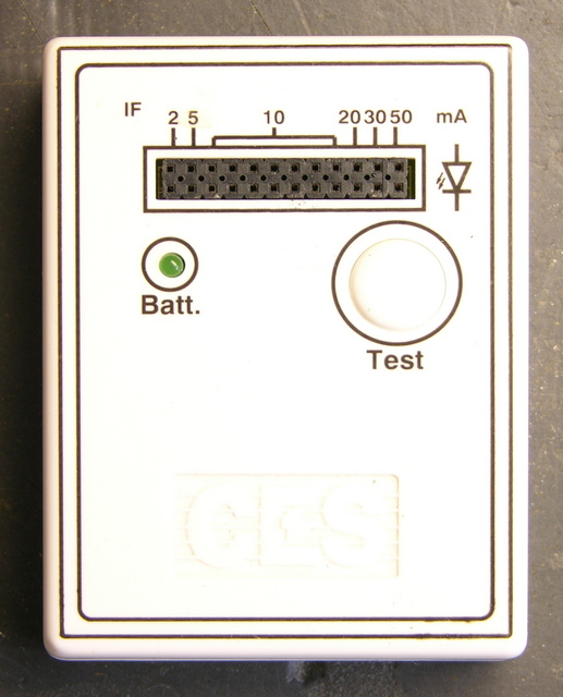
Oh, most of the time I use my LED tester to estimate the current I need for the brightness I like. At $6-10, it’s indispensible. Also double-checks anode/cathode pinning and tells me if an LED is burned out.

LED tester

But running on a 7.2V supply (NiMH “9V” battery) with fixed current-limiting resistors designed for a 9V supply and low-forward-drop LEDs, it’s not really representative of what’s going to happen when I put a newer-chemistry LED with a 3.5-4V drop into my 5V circuit. So it’s back to trial and error.

I want a microcontroller-based LED tester/calculator that:

  • has a socket for the LED
  • has controls to set the target-circuit supply voltage
  • has a current knob to turn until the LED is at a brightness I like
  • displays on an LCD the target circuit supply voltage, the LED voltage drop, the LED current, and the value of resistor to achieve that current with that supply voltage
    (That is, all the facts about the LED I’m testing, and the resistor value I need to use in the target circuit)
  • is about the size of my existing LED tester

Note that the tester need not be running at the target circuit’s voltage; we can calculate resistor values for arbitrary voltages once we know the desired LED current. It does need to have a higher supply voltage than the forward drop of new-fangled LEDs, and I’m inclined to run it on a 9V for compactness and simplicity.

I’ve been kicking this around for quite a while, and I’d really like to make one. And publish the plans and code for DIYers and make circuit boards and kits for kitbuilders.

Is that the right feature set? I personally never put LEDs in series, but should the tester be able to calculate for that anyway? What else?

How to Sort and Store Salvaged Electronic Parts

January 27th, 2008 by Keith Neufeld

Friday night, I harvested the components from this board using the heat gun.

Circuit board

Time spent

  • straightening leads with a chisel: 10 minutes
  • heating and pulling components: 15 minutes
  • sorting and putting away components: half an hour

And the sorting time would have been spent anyway if I’d bought the parts in a grab bag.

Salvaged electronic parts

The take:

  • several nice terminal strips, connectors, and a fuse holder
  • a handful each of electrolytic and non-electrolytic capacitors
  • a handful of resistors
  • a handful of diodes, including two Zeners and some 1N4007 rectifiers
  • miscellaneous transistors
  • miscellaneous ICs, including a speakerphone IC (ah! so this was a dead board from a campus emergency call system), tone generator and detector, low-power audio amplifier, and serial EEPROM
  • the inevitable transformer

Not bad, to my way of thinking, for an hour’s free entertainment.

Sorting and Storing

After salvage comes sorting and storing, which are mostly common sense. Here are some things I’ve found to minimize the tedium of sorting and to optimize storage.

My basic principle of sorting is to do so hierarchically. So I first group simmilar components, as shown above. Some components, like connectors and digital logic chips, go straight into bins without further sorting by type or value.

Connector and 7400 logic drawers

Resistors and capacitors I sort by decade (multiple of 10) immediately and by specific value later.

Sorted capacitors

If I find a batch of several identical capacitors, I like to keep them together in a small bag. If I’m working on a project and want identical caps for aesthetic or technical reasons, it’s easier to grab a bag than to pick through loose caps in a drawer.

Capacitor drawers

Then the capacitors (and bags) go into drawers labeled (approximately) by decade — electrolytics above, others below. Common values of physically larger caps may get split up into their own drawers.

Sorted resistors

It’s easy to pick out 10X-valued resistors while sorting by decade, so I do that up front (the upper row — 10Ω, 100Ω, 1KΩ, 10KΩ, and 100KΩ). The mixed resistors (lower row) go into a decade drawer

Resistor decade drawer

and get put into a row in the parts cabinet for now.

Resistor drawers

Then sometime later, I’ll go through the decade drawers and sort by individual value.

resistor tray

I’ve seen university EE stockrooms with enough parts bins to have every resistor value in a separate drawer, but most of us don’t have that much money or room for storage. I suggest going to hobby/craft stores and looking for storage solutions designed for beads or for embroidery floss. Bead storage in particular is good about sealing each compartment when the lid is closed, to keep beads resistors from migrating about when the storage is moved or shaken.

I spent several evenings driving all around Wichita a few years ago and came up with these trays, I think for floss, which are perfect for salvaged resistors. (New resistors may need the leads bent a bit to fit in the drawers.) I bought a tray for each decade and have a stack of them sitting beside my workbench.

Most of the resistors I salvage are 5%, which has 24 standard values per decade. I made a spreadsheet of all such values to fit on adhesive return address labels, Avery number 5267, and stuck a label into each spot in the tray. I’d offer the spreadsheet for download, but for some reason I can’t find it any more. :-(

How to Salvage Electronic Parts

January 19th, 2008 by Keith Neufeld

Knowing what kind of equipment to salvage for electronic components isn’t enough; you have to know how to get the parts out, or you’re just stockpiling junk. Through-hole ICs may be best stored on the original circuit boards to salvage when needed; but common components like resistors, capacitors, and diodes are much more economical to salvage in bulk, then sort, store, and have ready on demand.

I desolder with a heat gun and pull the components out with pliers. I destroy a few components on nearly every board I salvage; but it’s incredibly fast compared to any other method I’ve tried. For me, the time savings I discovered when I switched to using a heat gun was what made it really worthwhile to salvage components in bulk and stock up my parts bins.

Circuit board to salvage

Here’s a circuit board that one of the electricians at work brought me. I don’t know what it does; but he works a lot with the elevators and it’s probably something out of an elevator control system.

It’s not representative of the resistor- and capacitor-laden boards I particularly advocate salvaging; but I had it on hand and it does serve to demonstrate my method.

Uncrimping Component Leads

Through-hole components on commercially-produced boards tend to have their pins crimped on the solder side, to hold the components in place during the time between stuffing and soldering. Even with the solder melted, you can’t pull out a crimped component with pliers, so the first step is uncrimping the leads.

Uncrimping component leads with chisel

I use an cheap 1/4″-tip wood chisel from a dump bin at my local Ace Hardware store. (This is “my best $3 chisel” that I’ve referred to before — my real wood chisels never come anywhere near metal.) It doesn’t need to be sharp, but the edge should be fairly straight. I use a similarly cheap diamond honing board to clean up the nicked edge from time to time.

I push the chisel into the solder under the lead and lever up to straighten it. It’s important to get the chisel edge all the way to where the lead comes out of the hole, or you won’t be straightening the lead; you’ll be putting another zig in its zag.

Keep your other hand out of the path of the chisel. I’ve slipped the chisel off of leads, cut leads clean off, and tried to pry up solder pools that didn’t have leads in them. All of these result in a narrow, sharp object moving forward at high speed with a fair bit of pressure behind it. Again, think about where the chisel is going to go when it slips and keep your fingers out of the way.

It took only a couple of minutes to uncrimp the few leads on this board. Larger boards may take five to ten minutes; CRT motherboards can take half an hour, and I tend to do them in sections because uncrimping leads is really tedious and boring.

Heating and Removing Components

Once the leads are uncrimped, I clamp an edge of the board into my bench vise and get ready to heat it up. You need a bench vise that’s heavy or bolted down — you’re going to be prying and wiggling on the components quite a bit to get them out.

Still life with bench vise and heat gun

Now is a good time to remove fuses from holders, and optionally remove any socketed components from their sockets as well.

I use a cheap heat gun that I got for $15 at Harbor Freight. I regard it as a disposable item — I go through one in about a year (during which time I’ve salvaged far more than $15 of components) and go buy another.

Starting at the bottom edge of the board, I heat the solder side with the gun 1-2″ away until the solder melts, then pull out the components with a needlenose pliers and drop them in a cup. It’s faster and easier for me to put them in a container and sort them later than to place them carefully on my workbench and have them get brushed around, but your mileage may vary.

Some notes about the actual desoldering and component removal process:

  • The first component is going to take a long time to heat up. Be patient; pulling before the solder is fully melted will just break the part.
  • You can see the solder melt. Watch for it.
  • Start at the bottom and work up a column, angling the heat gun in the direction you want to go. It’ll start melting the next component’s solder while you’re removing the previous one. You can go quite fast on a stack of properly uncrimped resistors.
  • Get out the regular pliers for larger items, and particularly for DIP components. Rock them back and forth very gently until you can see that all the pins are loose, then slip them free.
  • Don’t hang onto a resistor lead with the pliers while you’re heating it — you’re just making a heatsink and preventing the solder from melting. Heat the solder, then grab quickly with the pliers and pull. You may get both leads in one pull; or you may get one end loose, readjust your grip, and get the other end.
  • TO-220 parts may fit tightly enough that they don’t want to come loose even after the solder melts. This can mean pulling the plating out of the through-holes, which then means cleaning the tubes off the leads later. A giant 3/8″ chisel-tip soldering iron laid across all three leads will pop a TO-220 free in an instant.
  • PC boards are flexible, especially when hot. Long strip connectors may require freeing one end and bending both connector and board as you work along the connector to free the remaining pins.
  • Larger heatsinks (PC power supplies and CRT motherboards) may have tabs that need to be untwisted, and their tabs or posts may fit tightly through barely large enough holes in the circuit board. If necessary, save them for last and force them out with large pliers.

This sounds obvious, but when you’re done desoldering, the circuit board is still hot. I hold it with pliers while loosening the vise, then lay it on the concrete floor to suck the heat out.

Scorched circuit board

Make no mistake, this is a destructive process. The circuit board will be ruined, and the fumes from scorched fiberglass are probably not good for your health nor for your relationship with your significant other or housemates. It’s best to do this as close to the outdoors as you can get and with windows open and forced air ventilation, if you have the option.

Finally, recycle the board if you can. We have a very thorough curbside recycling program here, and I’ve set out a large box of stripped circuit boards (with an appropriate note) for copper reclamation.

Sorting the Spoils

Here’s the cup into which I dropped the parts as I was pulling them:

Cup of salvaged electronic components

And the parts sorted on my workbench:

Salvaged electronic components

I got a couple of terminal strips, several DIP sockets (one irreparably damaged), four TTL ICs and two resistor packs, eight NPN transistors, diodes, LEDs, one capacitor, and fuses and fuse holders. Not great, but not bad for fifteen minutes’ work.

Repairing an InFocus LP290 Projector, Part 1

January 13th, 2008 by Keith Neufeld

A few months ago, I bought an InFocus video projector on eBay, still hoping to watch movies on the wall of the family room. It’s about 1/12 the size of the behemoth Sony projector I was trying to repair earlier, and quite a bit sharper and brighter; so if I can get it going, it’ll be a nice replacement.

When I received it, I immediately noted two problems: It shuts itself off after anywhere from seconds to hours; and it has a yellow silhouette running up the middle of the picture, kind of like the face/vase illusion.

I’ve taken some time this afternoon to disassemble and diagnose the projector; so although it’s not fixed yet, here’s what I know so far.

Chasing the Yellow Blob

In which Keith removes Crusty Gummy and washes a filter carrier

From the looks of it, I was pretty sure that the blob was going to be something wrong with, or wrong on the surface of, one of the lenses, mirrors, or filters. Yes, it looked a little like an LCD ruined by being left in a freezing car overnight, but not quite. So I dug in to follow the light path through the projector and see if it would be apparent what was wrong.

After popping the cover and removing the main circuit board, I could see most of the periscope-like light enclosure. I removed a couple of lenses that dropped in from above, which were clean, and looked at a couple of mirrors, which were also clean. The next thing I wanted to check was the LCDs.

Interior of InFocus LP290 Projector

In order to get to them, I had to take off the collar above/around them, remove the two cooling fan / speaker assemblies, and remove the main lens. The LCDs were mounted to the lens carrier and looked fine; their removal left access to this cavity where the RGB light paths converge.

LCD cavity on InFocus LP290 projector

I didn’t notice it until later, but someone had already been here before. Loctite on the RG screw tabs and missing from the B tab.

From a different angle, the problem was obvious.

Melted polarizing filter from InFocus LP290 projector

The filter between the blue light path and the blue LCD is all melty. Bad.

First things first. I gently peeled off the Bad, scrubbed all the goo off the glass carrier with Goo Gone, washed all the Goo Gone off with Dawn, rinsed the Dawn off with water, and dried the water off with a paper towel. (Life is sooooo complicated.)

Cleaned polarizing filter carrier from InFocus LP290 projector

Here it is all shiny and ready for . . . whatever comes next.

While I was in there, I detached and examined the other two filters. They didn’t look colored, just a light neutral grey in a very familiar sort of way. Apparently the filter isn’t what makes the blue blue (that’s the blue half-mirror further upstream), so maybe I can just put it back together and see what happens.

Reinstalling the Filter Carrier

Assembly is the reverse of disassembly.

The projector is back together and emitting blue light when it should be emitting black. The Bad was the polarizing filter that makes the LCD do its thing, so I’m going to have to find another one and put it back. It’s still emitting shades of blue; it just puts out quite a bit of blue when it should be going all the way to black.

I’d welcome donation of a spare polarizing filter from a differently-ruined LP290, and I’m shopping for a broken one. But partly for sheer “I can’t believe you did that and I can’t believe you got it to work” value, I’m sorely tempted to get a polarizing filter somewhere else and see whether it’ll do the job. Like a photographic filter. Or an LCD from dead equipment. Or sunglasses. :-)

Of course, none of those are good ideas. It obviously gets hot inside the projector, and meltage problems are going to avalanche as the filter warps and discolors and becomes less transparent and absorbs more energy from the light and heats up and warps and discolors. So I’ll at least look around for a spare projector to cannibalize.

Power Supplies

The projector has the lamp cover interlock switch and AC-DC power supply on the starboard side and the DC-DC power supply and lamp ballast on the port side. The AC-DC supply is always on, and the DC-DC supply appears to be under control of the microprocessor that runs the soft power button and monitors the sensors scattered throughout the projector.

The AC-DC power supply checks out okay, as far as I can tell. All of the electrolytics test good with my Capacitor Wizard, and the three voltages (16.5V, 6.6V, and 3.3V) are present on the edge connector that plugs into the main board.

I took the projector parts over to Ron Tozier, and he suggested testing all the voltages with the projector in standby, with the projector on, and after the projector shuts itself off. That should help determine whether the failure is in the AC-DC power supply board (probably not), in the DC-DC board, or quite possibly with one of the sensors. He also noticed that the main board has nicely labelled test points for lots of voltages, including not only the raw AC-DC supply outputs but also regulated and switched voltages under microprocessor control.

I printed out a digital pic of the main board, highlighted all the power supply test points and wrote the standby and on voltages next to them, and am now waiting for the projector to shut itself off. Of course it would pick now to stay on for hours.

I do note that every time I turn it on, as it powers up the lamp, I hear a chittering sound like an ultra-high-pitched buzzing. I think it’s the ballast going out, and I’m pretty sure the projector would sense a ballast failure and shut itself down. So I suspect I have a pretty good idea what I’m going to find is causing that problem as well.