Transistor-Based Variable Current Drive for LED Calculator

September 6th, 2010 by Keith Neufeld

I’ve put off working on my LED calculator project for far too long, at first trying to find the right handheld case to put it in and then later hoping to be able to manufacture a case myself. I’m not having any luck with that right now and if I keep waiting I’ll wait forever; so I’m resurrecting the project with the intention of selling it as a kit sans case.

The idea is to expand on a simple LED tester by allowing the user to plug in an LED, dial in the LED brightness, and then read information on an LCD showing the LED voltage drop, the current current, and the value of current-limiting resistor to use in a target circuit.

A microcontroller determines this information by measuring the voltage drop across a series current-sense resistor to calculate the current and measuring the voltage drop across the LED to calculate how much voltage will drop across the current-limiting resistor in the target circuit and what that resistor value should be.

Variable Resistor Drive

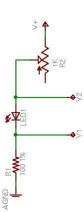
LED calculator drive circuit

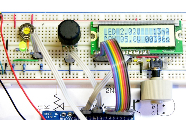
Until now, all of my prototyping has used a variable resistor in series with the LED to set the current. After subtracting the LED’s forward voltage drop from the supply voltage, the variable resistor dominates the resistance of the remaining series chain (which includes the current-sense resistor), thereby setting the series current.

LED calculator prototype with direct potentiometer drive

This does give control over the LED current and brightness, but the problems with this method are:

  • A small-valued potentiometer doesn’t provide enough resistance to dial down to low enough LED currents. For example, a 1K pot with the circuit running on 9V won’t deliver less than 6mA, depending on the LED color (and voltage drop); and modern, high-efficiency LEDs are surprisingly bright at 6mA.
  • A large-valued potentiometer has an extremely non-linear current response, with all the “action” at the very end of its rotation.

Here’s the response of two different LEDs with a 10K potentiometer:

Position Green LED Current Blue LED Current
0 1mA 1mA
1 1mA 1mA
2 1mA 1mA
3 1mA 1mA
4 1mA 1mA
5 2mA 2mA
6 3mA 2mA
7 4mA 3mA
8 5mA 6mA
9 34mA 21mA
10 100mA 89mA

Very slow response until near the end of the potentiometer’s rotation, at which point the response is so rapid that it’s very difficult to control
And of course this makes sense, as it’s the hyperbolic curve of I = V/R.

Transistor Drive

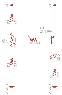
Last week I started looking at improving the range and linearity of the LED current. I’m not looking for a perfectly flat response curve nor for a true constant-current drive; I just want a somewhat better response. What came to mind was this simple PNP transistor circuit — actually an even simpler version without R1 and R3, but I’ll explain their purposes in a bit.

Transistor LED current control circuit

The theory is that R2 (or R1 + R2 + R3) acts as a voltage divider across the power supply, linearly setting a drive voltage. R4 (nearly) linearly turns this voltage into a current sink across the PNP transistor’s emitter-base junction; and because R4 >> R2, R2 presents a “stiff” voltage source to R4, meaning we can largely ignore R4′s effects on the voltage division.

Thus R2 provides (nearly) linear control of the emitter-base current. In the common-emitter configuration, the PNP transistor amplifies the current by the transistor’s β (about 150-200 for a small, general-purpose PNP like the 3906) for a correspondingly higher emitter-collector current

IEC = β IEB

which goes through the LED and the sense resistor, providing (nearly) linear control of the LED brightness by turning R2.

Well, that’s the theory, anyway. This weekend I dug out the prototype and built up the transistor control to test it in practice.

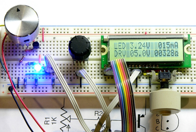
LED calculator prototype with transistor current drive

(70s decor courtesy Radio Shack.)

The first thing I noticed was a section at the CCW end of R2′s travel in which nothing happened, because R2 wasn’t providing more than the transistor’s cut-in voltage — that is, although VB was less than VE, it wasn’t enough less to overcome to emitter-base forward voltage drop and bias the transistor down into the active region.

I tried installing a small-signal diode “above” the potentiometer so that VB would always be at least .6V below VE and eliminate R2′s dead region, but the diode’s forward voltage drop was a little too high (it did too good a job) and the resulting minimum LED current was a little higher than I liked. I settled on adding R3 in that position, selecting 68Ω as a value that worked well with both traditional and high-power / high-efficiency LEDs and with both 9V and 7.2V supplies.

With a 9V supply and R3 = 68Ω, I tried three different values of the base resistor R4.

R2 Position R4 = 10kΩ R4 = 22kΩ R4 = 47kΩ
Green Blue Green Blue Green Blue
7:00 0mA 0mA 0mA 0mA 0mA 0mA
8:00 0mA 0mA 0mA 0mA 0mA 0mA
9:00 8mA 7mA 3mA 2mA 1mA 1mA
10:00 30mA 30mA 15mA 13mA 7mA 6mA
11:00 46mA 42mA 24mA 22mA 13mA 11mA
12:00 56mA 47mA 34mA 32mA 17mA 17mA
1:00 60mA 48mA 42mA 40mA 24mA 22mA
2:00 62mA 49mA 49mA 44mA 29mA 26mA
3:00 62mA 49mA 53mA 46mA 32mA 30mA
4:00 63mA 49mA 55mA 47mA 34mA 31mA
5:00 63mA 49mA 55mA 47mA 34mA 32mA

The table shows a similar effect at the other end of R2′s travel in which the LED current was pretty well maxed out and not increasing any further. I think I was hitting the knee between the transistor’s linear region and saturation, meaning increasing IEB was no longer increasing IEC. Experimentation gave me R1 of 200Ω keeps the transistor pretty well out of saturation and gives a satisfyingly more-linear response than what I measured here.

The 0mA readings at the beginning of the table, by the way, are a bit deceptive — some of my test LEDs are actually lit in that region. I’ve updated the Arduino code to show tenths of a milliamp when the reading is below 10mA, and I can see LEDs glowing with as little as .1mA. Probably not a value of interest for most people, but it could be effective for making flickering gas lamps for model railroads.

Choosing Values

R4 = 22kΩ looks like a pretty good compromise between providing a near-linear response and covering the range of LED currents I expect most people would be interested in testing, so I’ve tentatively settled on it.

I’m still fiddling with values to give good performance at both 9V (alkaline battery) and 7.2V (NiMH), because I use rechargeables almost exclusively and want to make this work well on rechargeables to encourage other people to do the same. The problem is,

Vsupply = 7.2V
VEC ≈ .8V
Vblue LED ≈ 3.5V

VR5 = Vsupply – VEC – VLED = 7.2V – .8V – 3.5V = 2.9V

ILED = IR5 = VR5 / R5 = 2.9V / 100Ω = 29mA

In other words, running on a 7.2V battery, with the transistor saturated, a blue LED with a 3.5V forward drop maxes out at 29mA; and it gets worse with a battery that’s not straight out of the charger and some white LEDs with a higher forward voltage drop. I’d like to enable people to test up to 50mA, to cover high-brightness LEDs, so I’d like to push this maximum current a little higher.

R5 = 68Ω gives ILED up to about 42mA, which isn’t as high as I like; but the tradeoff is that a smaller R5 gives me a smaller voltage range to sample in the A/D converter, hence lower resolution for the display. 68Ω seems like a good compromise. And I’m already thinking about a DPDT switch to change the resistor and alert the microcontroller about battery chemistry.
Repairing a Crumar T1 Organ Swell Pedal

August 6th, 2010 by Keith Neufeld

Crumar stack

Both my Crumar T1 and T2 “portable” organs (the lower two cases in the stack) came to me without swell (volume) pedals. Each has a rotary potentiometer on its control panel for master volume, but I really want to be able to change the volume dynamically while playing. I’ve been using a Dunlop volume pedal (built into a rocker case identical to the CryBaby wah) on the organ’s output; but (at least when used with the organ) all of the pedal’s action is in about the lower quarter of its physical range, so it’s very finicky to use.

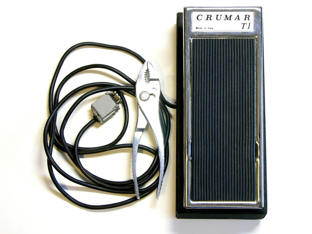
Crumar T1 organ swell pedal

I recently bought this original T1 swell pedal on eBay, listed as untested / project. That usually means tested / didn’t work / can get more money if I don’t admit that I already know it doesn’t work; but I figured I could fix whatever was wrong with it. And I have.

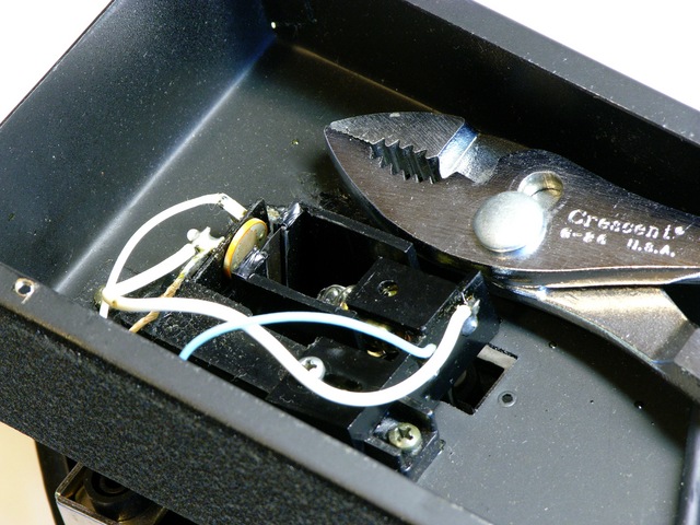
Crumar T1 organ swell pedal photoresistor enclosure

Read the rest of this entry »

Repairing a Bad Horsie 2 Wah Pedal with Power Damage

July 7th, 2010 by Keith Neufeld

Bad Horsie 2 wah pedal

I recently ran across on Craigslist a

Bad horsie 2 that was plugged into the wrong power supply and messed up, and needs some minor electronic work.

I was intrigued by the challenge (I’m such a sucker for broken things, dang it) and bought it. When the seller and I exchanged the pedal for my cash, he remarked that he read on a forum that it probably just needed a resistor changed, and that if I were handy with a soldering gun I could probably do it myself.

Uh huh. Resistor.

Let’s dig in.

Bad Horsie 2 wah pedal circuit board

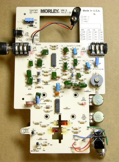
The circuit board has a hole in the top for a foam battery “cage” attached to the enclosure, something clever that I haven’t seen before. And it had no obviously damaged components.

Read the rest of this entry »

Installing Batteries in a Liebert GXT2-2000RT120 UPS

June 27th, 2010 by Keith Neufeld

A while back, I bought a secondhand Liebert GXT2-2000RT120 uninterruptible power supply (UPS) on eBay. The GXT2 is a series of online UPSes, meaning that the output power always comes from the inverters off the battery bank; it doesn’t switch from utility power to battery power like an offline UPS. Besides eliminating any possible switchover glitches, online UPSes always deliver conditioned power at a constant voltage. The 2000RT120 is a 2000VA unit with 120V output — large enough to power all my servers for a good little while.

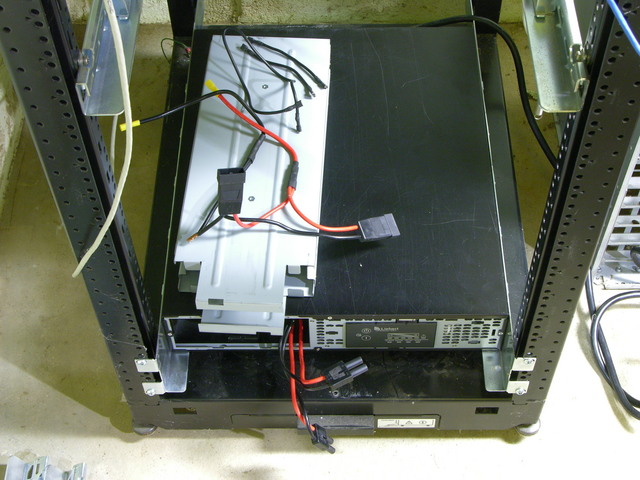
Liebert GXT2-2000RT120 UPS with battery cage disassembled

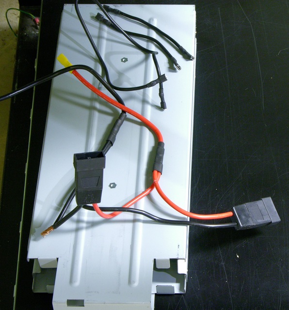
The batteries were due for replacement and the seller removed them to save on shipping costs. I got a UPS with a set of wires and no instructions on how to connect them.

Liebert GXT2-2000RT120 UPS battery wiring

Also one of the wires was compromised … but since it appears to be a ground wire, I figured no big deal if it shorts out against the cage. KIDDING!

Yesterday I figured out the wiring, installed batteries, and got the UPS set up in my server rack.

Read the rest of this entry »

Q&A: PIC Programmer, Oscilloscope

June 19th, 2010 by Keith Neufeld

I get very specific questions via my contact form, but also questions about more general issues that might be of interest to a larger audience. I’m going to start posting the latter category here.

PIC Programmer

Trey asks:

Do you have any recommendations regarding a Microchip programmer? There is the PicKit 2 and the Pickit 3. I have read that there are/were issues with the PicKit 3. I know you have used Microchip parts in your designs, but was wondering what your opinion was?

Trey, I’ve never used a PIC that wasn’t already preprogrammed with the LogoChip environment, so I have no experience with PIC programmers.

After reading through PIC and Atmel datasheets in considerable detail to access hardware features on both platforms, my opinion is that I’ll never use a PIC. That’s based on a couple dozen small things that I don’t even remember any more, but which added up to a pretty powerful opinion that Atmel builds a much better thought-out microcontroller that’s much easier to use.

But … that’s not the answer you were looking for. Readers with PIC experience, can you address Trey’s question? Please clearly phrase your responses as statements of opinion (like my opinion above, which is nothing more than an opinion) or as statements of fact with links to supporting information.

Oscilloscope

I am just now starting my journey into electronics and was wondering if you have any recommendations for any particular make/model of oscilloscope?

For someone starting in electronics, before an oscilloscope, I would recommend:

  • A $3 multimeter. I’ve started buying a few of these whenever I go to Harbor Freight and find them on sale, and I give them away like candy. Ace Hardware also sometimes has cheap meters in the dump bin.

    Is this as accurate as a Fluke? Of course not — but for basic electronics troubleshooting, this is more than adequate. The one useful function it lacks is a beeper for continuity testing — you do have to look up at the screen to read low resistance.
  • A breadboard and some components with a list of projects to try. I’d suggest Adafruit’s $50 Arduino budget pack, $65 Arduino starter pack, or $85 Arduino experimentation kit. Even if you’re not that interested in embedded design, the Arduino is a great platform for trying things out and interfacing to the analog electronics, and the Adafruit kits provide a list of experiments to use as a starting point and get the ideas flowing.

But if you’re already doing PIC programming, you seem to be well past the resistors-and-LEDs stage. If you really need a way to visualize signals in order to progress, my oscilloscope recommendation would be whatever working scope you can get for the lowest price, making sure that you do end up with at least one probe (or find a cheap one on eBay).

I paid $25 for an old, used scope about 20 years ago and have only upgraded to a better scope in the last couple of years — which is 20 years old, which I got from a friend of a friend, and which I haven’t put on my bench and started using yet.

The two times I’ve used a different scope are when I found a cheap scope with X-Y inputs that I use for troubleshooting vector arcade game displays, and when I borrowed a digital Tek scope for doing some precise high-frequency measurements.

Granted, I don’t use my scope for calibrating circuits. If you need to do that, you need a better scope, and one that’s calibrated, and that’s going to cost real money. But if visualization is what you’re after, then the cheapest scope that works will do the job.

Lacing the x0xb0x Wiring Harnesses

June 6th, 2010 by Keith Neufeld

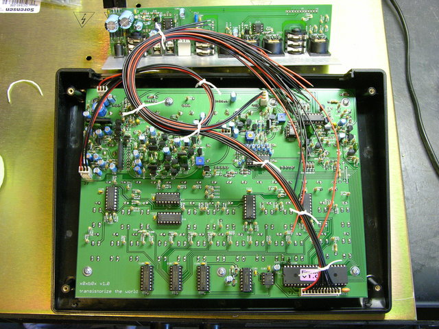
This isn’t part of a normal x0xb0x build so I didn’t throw it into my build notes, but I had fun figuring out how to route and lace the x0xb0x’s wiring harnesses. I know lacing is overkill for this; but without some kind of cable management, the individual wires of each cable wouldn’t even stay together. Had the kit included ribbon cables, I wouldn’t have bothered.

Planning the Paths

First pass at x0xb0x cable routing

Besides the obvious goal of keeping the wires tidy, my main goal was to position slack in the cables so that the back panel could be lifted out of the case and set to the rear, allowing full access to both circuit boards, without disconnecting anything.

Before doing any real lacing, I mocked up the cable path to make sure everything would work. My first attempt, here, had enough length for the J3 bundle from the lower right of the main board to the right end of the I/O board; but J7′s wires coming from the left edge of the main board looped around too much before heading to the I/O board and didn’t reach their destination.

Read the rest of this entry »

Building the x0xb0x

June 6th, 2010 by Keith Neufeld

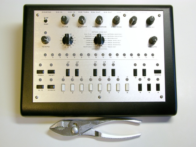
As I noted previously, I recently got a x0xb0x kit. The x0xb0x is an open-source-hardware replica of the 1980s Roland TB-303 bassline synthesizer (and sequencer) that was influential in the development of acid house music. Limor of Adafruit Industries and a mysterious, anonymous German studied the TB-303 schematics and measured the behavior of its now-rare semiconductors and designed a replica with the same analog circuitry and new digital features, including MIDI I/O (supplementing Roland’s pre-MIDI “DIN sync”) and simpler sequencer programming.

Assembled x0xb0x, top view

Adafruit produced x0xb0x kits in batches of 100 as Limor was able to track down enough “rare parts,” order circuit boards, and assemble the common parts into kits. I’d been on her waiting list since 2008, so was terribly disappointed when she officially announced what we had all come to realize anyway — that tracking down the rare parts was becoming enough of a hassle, she wasn’t having any fun doing it and wasn’t going to produce any more kits.

Happily, Limor announced shortly thereafter that thanks to Adafruit’s open-source hardware license, James Wilsey of Willzyx Music in Taiwan has taken up the torch and would shortly be offering x0xb0x kits.

Read the rest of this entry »

MIDI Looper?

May 31st, 2010 by Keith Neufeld

I’m starting to think I’d like a MIDI sequencer that behaves somewhat like a looper, doing the following:

  • Capture a short sample of a MIDI performance, including key velocity data.
  • Quantize to a tempo set by a “tap tempo” pedal continually and dynamically throughout the capture, rather than to an LED or click track.
  • Loop and play back, by default to the last tempo seen but honoring continuous “tap tempo” data from the same pedal.

Using a MIDI sequencer with these “tap tempo” features should give greater flexibility for capture and playback during a live ensemble performance than using a traditional audio looper, which requires the whole ensemble to play to the tempo recorded in the loop.

But my real motivation is to be able to play a pattern and then make gradual, multi-bar changes to the analog character of the sound without having to continue playing with one hand and turn knobs with the other.

Record a one-bar pattern on a MIDI keyboard driving a x0xb0x (or a real TB-303, if you’re filthy rich enough to have one and a DIN-sync MIDI adapter to go with it), then play it back and slowly tweak the knobs while everyone else jams on for a bit.

Am I going to find that all of this functionality already exists within the x0xb0x? (It looks like it might be close — MIDI ports; internal sequencer; variable tempo, although perhaps not that sophisticated.) Alternatively, are there MIDI sequencers that do all of this? Is this de rigeuer for every sequencer under the sun?

Repairing a Patch Cord

May 31st, 2010 by Keith Neufeld

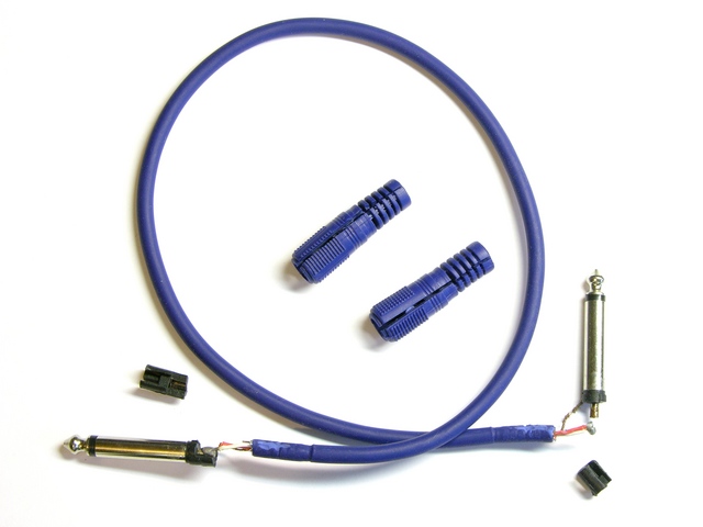
Recently a couple of pieces of audio processing equipment I’ve bought used have had bad left channels. After recognizing the pattern, I finally thought to swap out the patch cord I had left plugged into the “test” channel on my keyboard mixer, and voila! Left channels fixed.

Audio patch cord, disassembled

I’ve always been curious about the construction quality of commercial patch cords — just how good are the connections buried under those lovely molded jackets and strain reliefs?

Naturally, the faulty end was the last one I disassembled. (Logic joke!)

Read the rest of this entry »

EasyBright on Stage

May 25th, 2010 by Keith Neufeld

Music stand wand light with lens flare

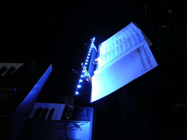
Saturday night the EasyBright already got its public debut! I played a pair of classic rock concerts Friday and Saturday nights, and Friday had trouble seeing my music (occasionally folded out to four pages) with the clip-on stand light I was using. Saturday after assembling the EasyBright, I built an LED “wand” music stand light that worked marvelously.

End of LED wand music stand light

I didn’t have a lot of time for construction, so I cut a 1/2″ dowel to 3′ length and drilled eighteen 1/8″ holes through it (axially, not longitudinally) every 2″. Paint wouldn’t dry before the show, so I sanded the dowel and then colored it with a permanent marker. I then installed bright flat-top LEDs with a good viewing angle into the holes and bent the leads out in opposite directions.

Wiring on LED wand music stand light

I lap-soldered teflon-insulated (heat-resistant) wire from LED to LED with heat-shrink tubing preinstalled — but didn’t shrink the tubing until after I had tested the LEDs, in case I needed to repair any solder joints. I skipped LEDs to make an A-B-C-A-B-C pattern so if a chain failed, I’d lose light evenly along the whole wand instead of all in one section.

Connectors at end of LED wand music stand light

I crimped connectors onto the wires, connected everything to the EasyBright, put an appropriate connector on a 24VDC wall wart, and fired it up perfectly on the first try. (Such luck!) I disconnected the wand, reseated and shrank the heat-shrink, zip-tied the wires in place, and then powered up the wand to burn in for an hour before leaving home for the concert.

LED wand music stand light

On stage, it delivered a very even wash of illumination across my music, giving me a great view all through the show.

EasyBright circuit board driving LED wand music stand light

The circuit board is so lightweight, it was comfortably suspended in mid-air between the keyboard rack and my music stand by the power and LED wires. For the long term, I’m trying to decide whether how it should be mounted to the wand — perhaps attached near the end inside a sleeve of giant heat-shrink.